
HEADLAMP — Headlamp Aiming Control — Description (Cont'd) / Circuit Operation / Headlamp Aiming — Adjust
EL-50prose procedureThree-figure storyboard (SEL659F/660F/661F) explains the closed-loop logic at switch-step granularity. The motor moves only while the brushes are on the conductive segment — when they land on the white sector the circuit opens. Repeat moves chain together to reach positions 2/3.
Description (Cont'd)
CAUTION
Aiming motor unit can not be disassembled.
CIRCUIT OPERATION
[Example]
Aiming switch "0"
NOTE
• When the aiming switch is set to "0", the motor will not start because the power terminals are positioned at the non-conductive section of the sensor's rotary unit.
Aiming switch "0" → "1"
NOTE
• When the aiming switch is moved from "0" to "1", power is applied to the motor through the sensor's conductive section. The headlamps will then move in the "DOWN" direction.
• The motor continues to rotate while the rotary unit of the sensor moves from point A to point B.
• The power terminals will then be positioned at the non-conductive section, disconnecting the power to the motor. Then motor stops.
Aiming switch "1" → "0"
NOTE
• When the aiming switch is moved from "1" to "0", power is applied to the motor through the conductive section of the sensor. The motor will rotate to move the headlamps in the "UP" direction.
• When the rotary unit of the sensor moves from point B to point A, the motor will stop.
HEADLAMP AIMING — Adjust
- 1Horizontal aiming of the headlamp is achieved by adjusting the top adjusting screw as detailed for non-headlamp aim version.
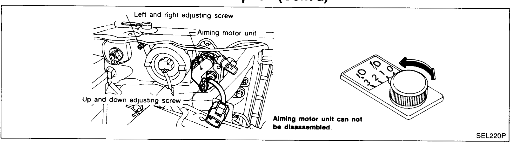 SEL220P
 - 2Vertical aiming of the headlamp is achieved in the same way as for non-headlamp-aim versions, except that the aim adjusting screw is situated on the back of the headlamp aim motor.
 SEL251P