
Parts Diagrams
Exploded views and component parts lists from the service manual — 82 diagrams across 13 sections, 1075 individual parts
Engine Mechanical
EM21 diagrams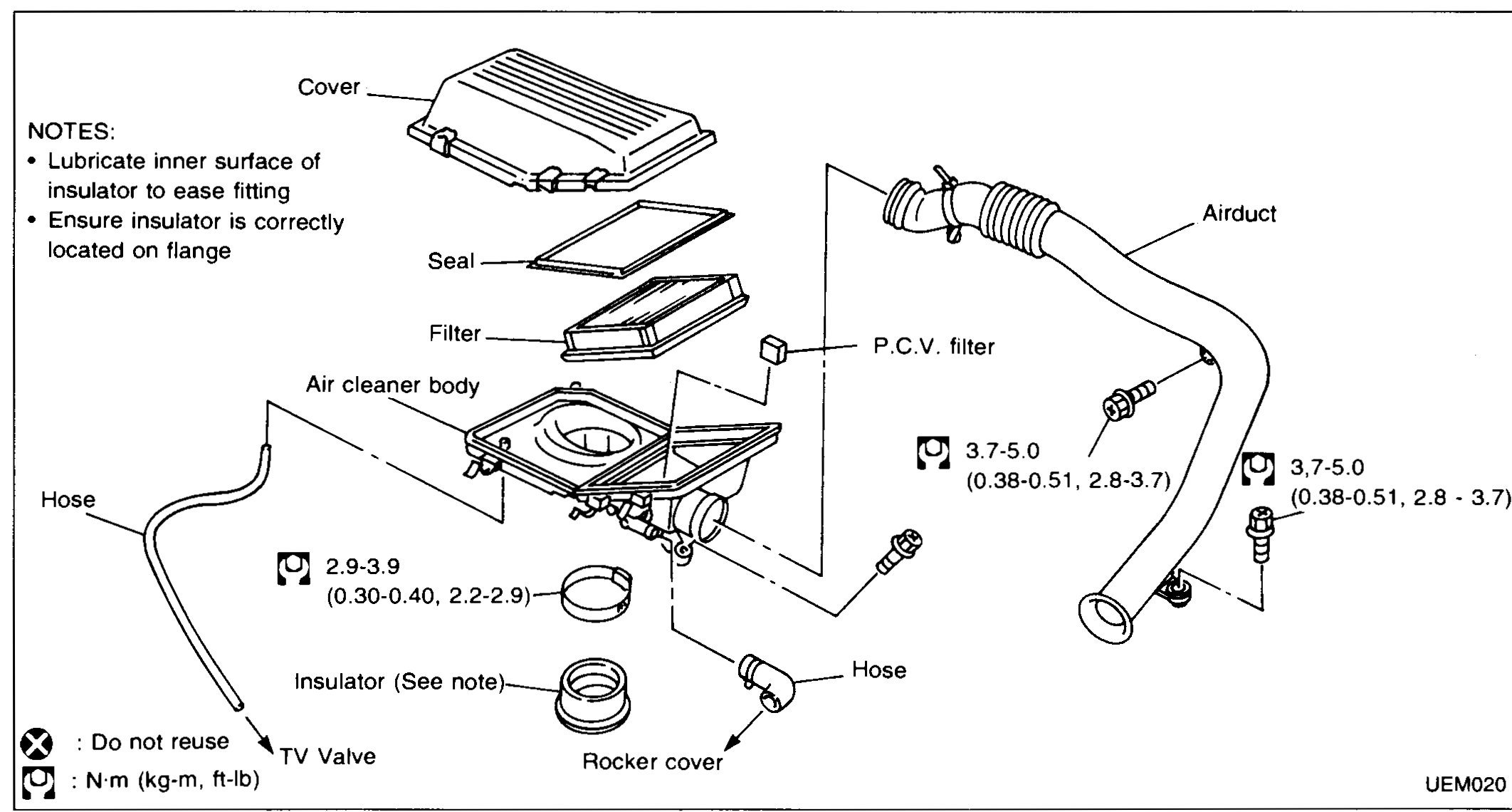
OUTER COMPONENT PARTS — Air Cleaner / Intake Manifold & Fuel System
EM-7Air cleaner assembly exploded view with: Cover, Seal, Filter, P.C.V. filter, Air cleaner body, Insulator (See note), Rocker cover, Hose, Airduct, TV Valve. Torque annotations: 2.9-3.9 N·m (0.30-0.40 kg-m, 2.2-2.9 ft-lb) and 3.7-5.0 N·m (0.38-0.51 kg-m, 2.8-3.7 ft-lb). Notes: "Lubricate inner surface of insulator to ease fitting" and "Ensure insulator is correctly located on flange". Legend symbols: ⊗ = Do not reuse; torque wrench symbol = N·m (kg-m, ft-lb).
OUTER COMPONENT PARTS — Air Cleaner / Intake Manifold & Fuel System
EM-7Air cleaner assembly exploded view with: Cover, Seal, Filter, P.C.V. filter, Air cleaner body, Insulator (See note), Rocker cover, Hose, Airduct, TV Valve. Torque annotations: 2.9-3.9 N·m (0.30-0.40 kg-m, 2.2-2.9 ft-lb) and 3.7-5.0 N·m (0.38-0.51 kg-m, 2.8-3.7 ft-lb). Notes: "Lubricate inner surface of insulator to ease fitting" and "Ensure insulator is correctly located on flange". Legend symbols: ⊗ = Do not reuse; torque wrench symbol = N·m (kg-m, ft-lb).
OUTER COMPONENT PARTS — Intake Manifold & Fuel System (Cont'd)
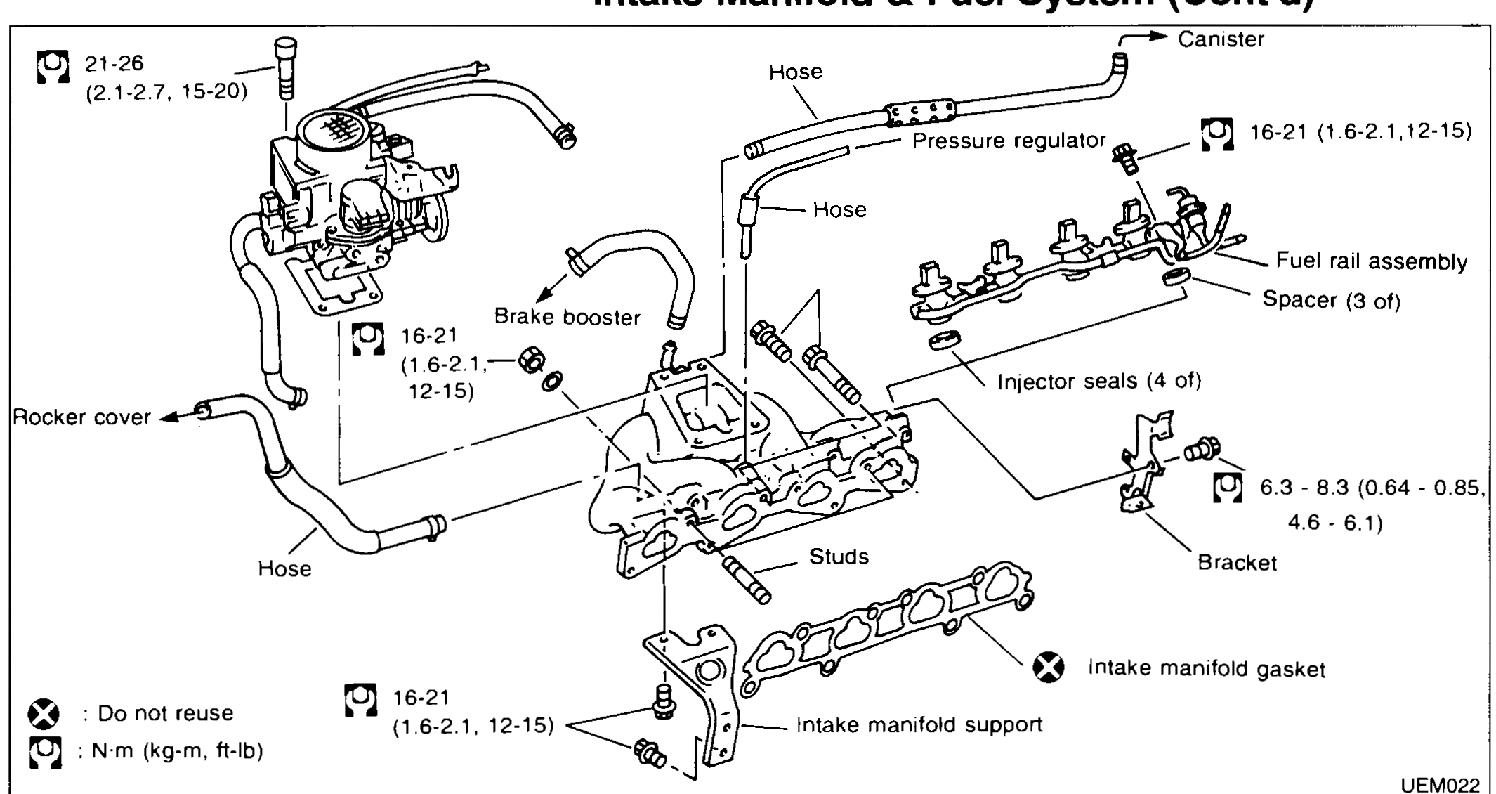
EM-8Exploded view of intake manifold and fuel rail. Components: Hose (×2), Canister, Pressure regulator, Fuel rail assembly, Spacer (3 of), Injector seals (4 of), Bracket, Intake manifold support, Intake manifold gasket, Studs, Brake booster connection, Rocker cover, Hose. Legend bottom-left: ⊗ Do not reuse; torque symbol = N·m (kg-m, ft-lb). Torque callouts: 21 - 26 (2.1 - 2.7, 15 - 20), 16 - 21 (1.6 - 2.1, 12 - 15) (multiple instances), 6.3 - 8.3 (0.64 - 0.85, 4.6 - 6.1).
OUTER COMPONENT PARTS — Intake Manifold & Fuel System (Cont'd) / Fuel Rail Removal & Inspection
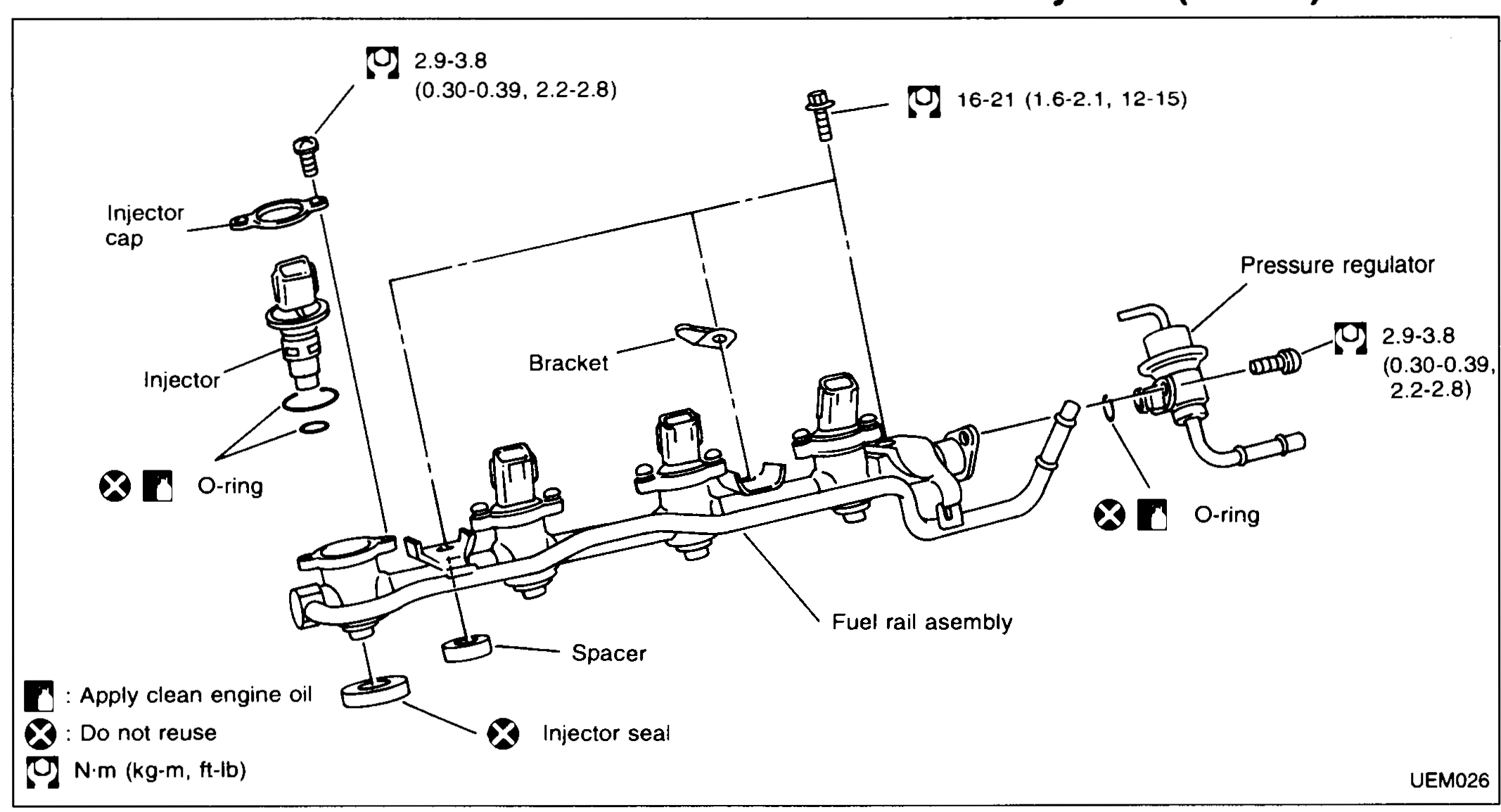
EM-9Fuel rail assembly exploded view. Components left-to-right: Injector cap, Injector (×4), O-ring (Apply clean engine oil; Do not reuse), Bracket, Fuel rail assembly, Spacer, Injector seal (Do not reuse), Pressure regulator with O-ring (Apply clean engine oil; Do not reuse). Torque annotations: 2.9-3.8 N·m (0.30-0.39, 2.2-2.8) at injector cap and pressure regulator; 16-21 N·m (1.6-2.1, 12-15) at fuel rail bracket bolts. Legend: oil-can symbol = Apply clean engine oil; ⊗ = Do not reuse; torque wrench = N·m (kg-m, ft-lb).
OUTER COMPONENT PARTS — Exhaust Manifold and Catalyser / Removal / Inspection / Assembly
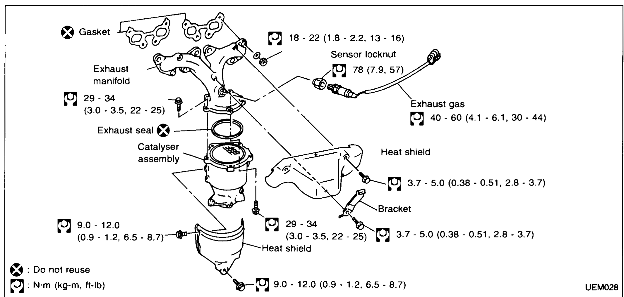
EM-10Exhaust manifold and catalyser exploded view with: Gasket (Do not reuse), Exhaust manifold, Exhaust seal (Do not reuse), Catalyser assembly, Sensor locknut, Exhaust gas (sensor), Heat shield, Bracket. Torque annotations: 29-34 N·m (3.0-3.5, 22-25) at exhaust manifold studs; 9.0-12.0 N·m (0.9-1.2, 6.5-8.7) at catalyser brackets; 78 N·m (7.9, 57) sensor locknut (single value); 18-22 N·m (1.8-2.2, 13-16) at heat shield bracket; 40-60 N·m (4.1-6.1, 30-44) at exhaust gas sensor; 3.7-5.0 N·m (0.38-0.51, 2.8-3.7) at heat shield screws (two locations). Legend: ⊗ = Do not reuse; N·m (kg-m, ft-lb).
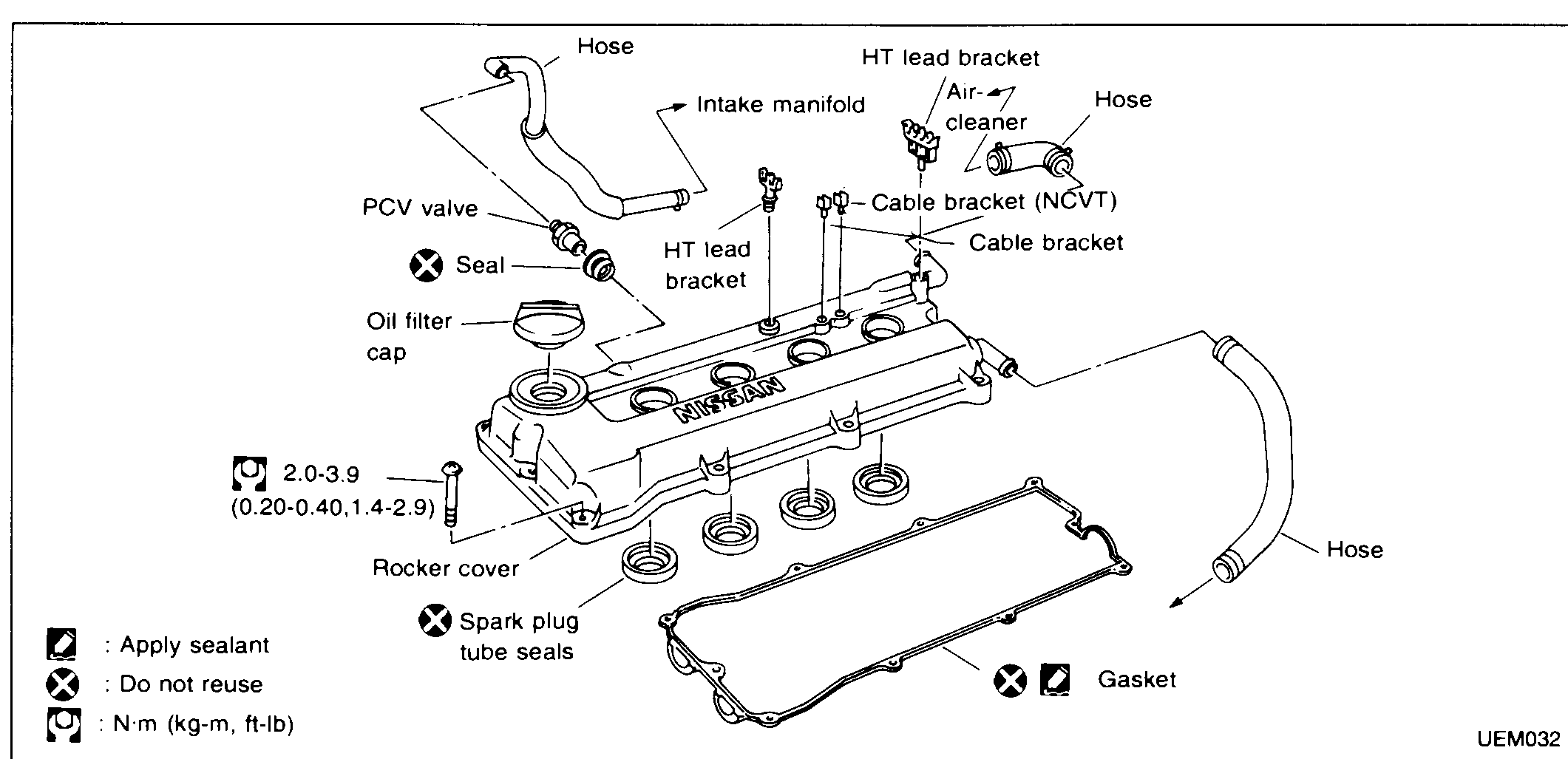
OUTER COMPONENT PARTS — Rocker Cover / Removal / Assembly
EM-11Rocker cover exploded view with: Hose (PCV), Intake manifold side, HT lead bracket (×2), Air cleaner side, Hose, PCV valve with Seal (Do not reuse), Oil filler cap, Cable bracket, Cable bracket (NCVT), Rocker cover, Spark plug tube seals (Do not reuse), Gasket (Apply sealant + Do not reuse), Hose. Torque annotation: 2.0-3.9 N·m (0.20-0.40, 1.4-2.9) at rocker cover bolts. Legend: oil-can symbol = Apply sealant; ⊗ = Do not reuse; torque wrench = N·m (kg-m, ft-lb).
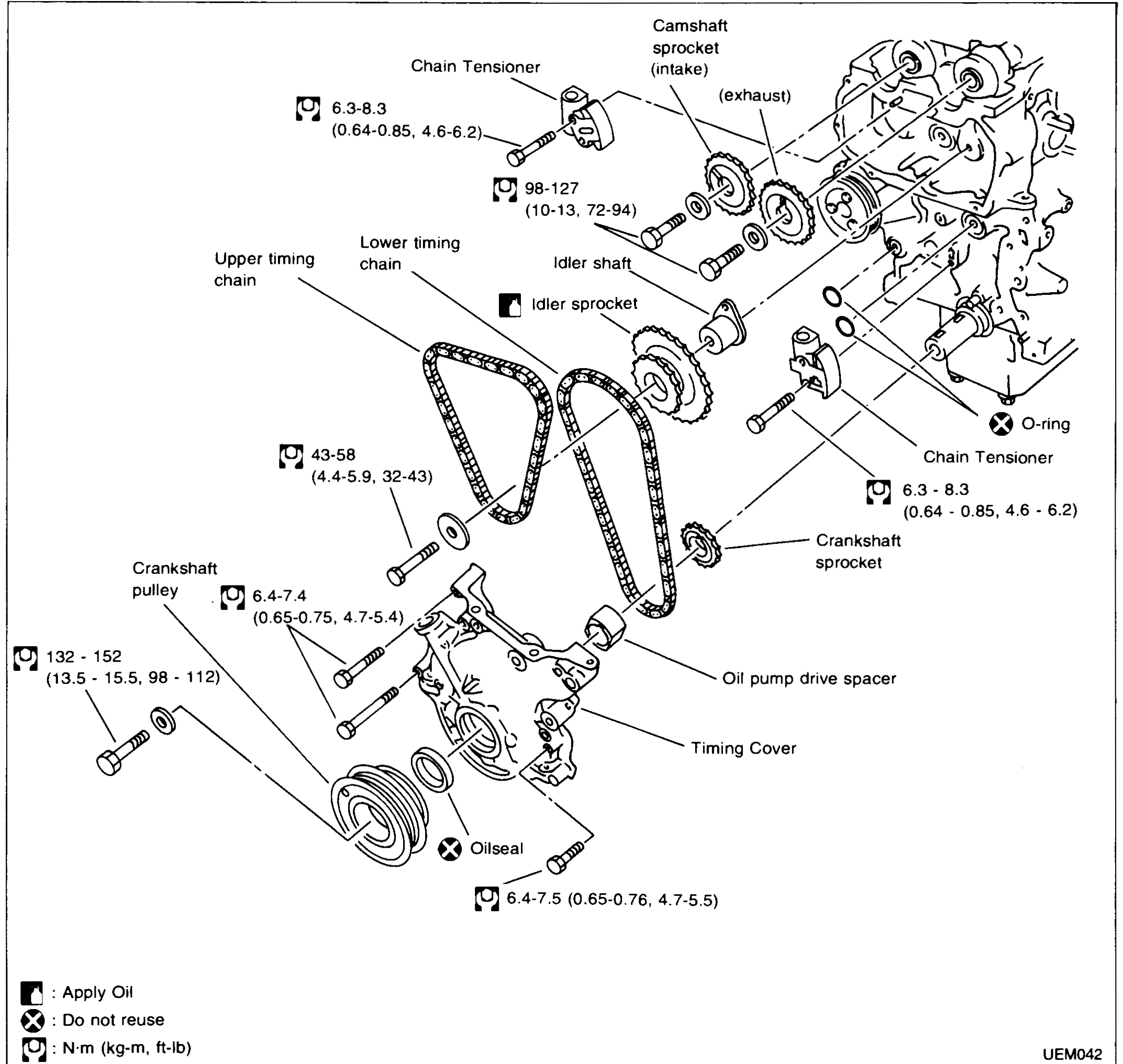
TIMING CHAIN — Exploded View
EM-16Timing chain exploded view. Components labelled: Chain Tensioner (upper), Camshaft sprocket (intake), Camshaft sprocket (exhaust), Upper timing chain, Lower timing chain, Idler shaft, Idler sprocket, O-ring (Do not reuse), Chain Tensioner (lower), Crankshaft sprocket, Crankshaft pulley, Oil seal (Apply oil; Do not reuse), Oil pump drive spacer, Timing Cover. Torque annotations labelled with torque-wrench symbol: 6.3-8.3 N·m (0.64-0.85, 4.6-6.2) at upper chain tensioner; 98-127 N·m (10-13, 72-94) at camshaft sprocket bolts; 6.3-8.3 N·m (0.64-0.85, 4.6-6.2) at lower chain tensioner; 43-58 N·m (4.4-5.9, 32-43) at idler-shaft bolt; 6.4-7.4 N·m (0.65-0.75, 4.7-5.4) at timing cover bolts (upper); 132-152 N·m (13.5-15.5, 98-112) at crankshaft pulley bolt; 6.4-7.5 N·m (0.65-0.76, 4.7-5.5) at timing cover bolts (lower). Legend: oil-can symbol = Apply Oil; ⊗ = Do not reuse; torque-wrench symbol = N·m (kg-m, ft-lb).
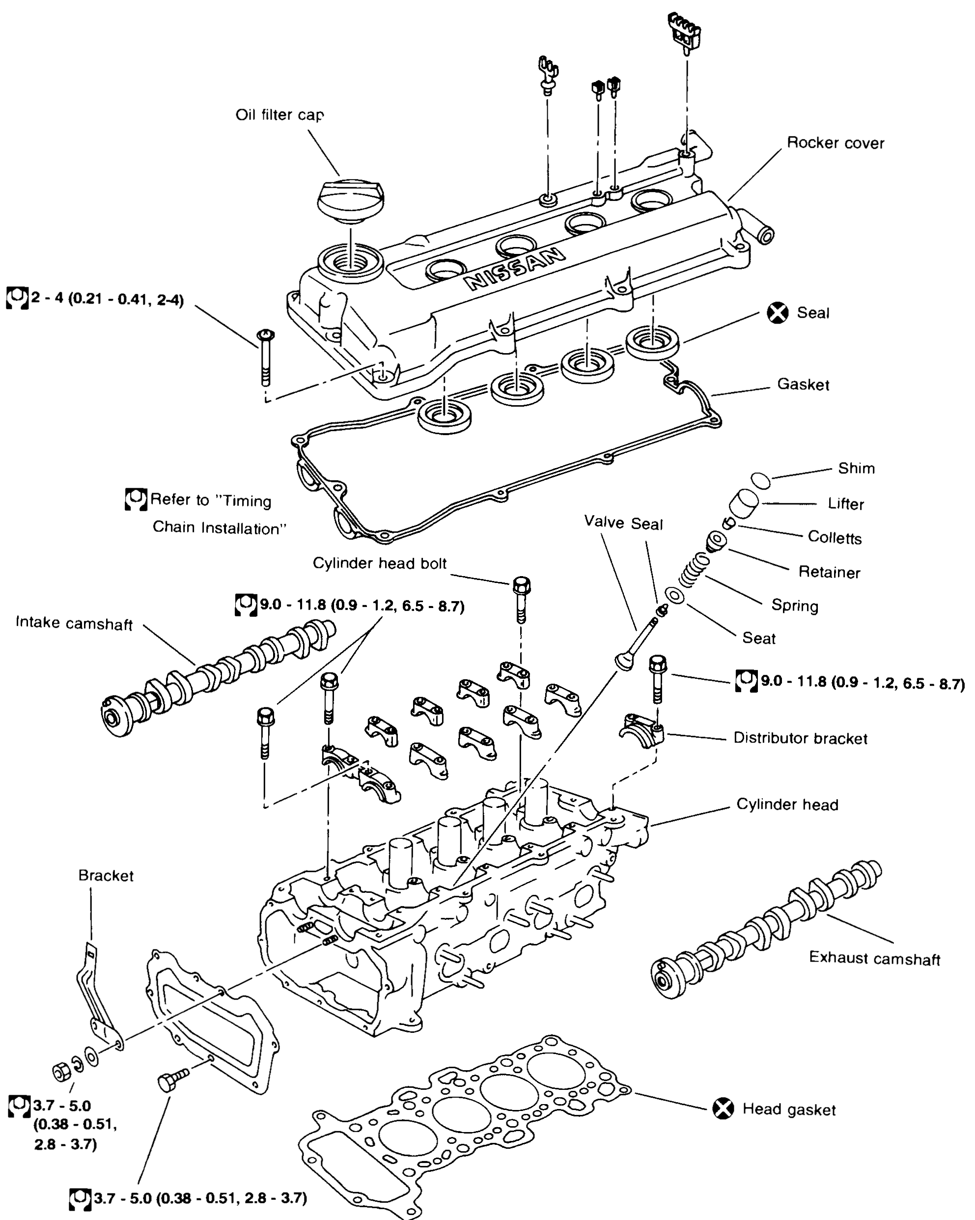
CYLINDER HEAD — Exploded View
EM-28Cylinder head exploded view with: Oil filler cap, Rocker cover (with NISSAN logo), Seal (Do not reuse), Gasket (rocker cover), Shim, Lifter, Colletts, Retainer, Spring, Valve Seal, Seat, Cylinder head bolt, Intake camshaft, Bracket, Distributor bracket, Cylinder head, Exhaust camshaft, Head gasket (Do not reuse). Torque annotations: 2-4 N·m (0.21-0.41, 2-4) at rocker cover bolts; "Refer to 'Timing Chain Installation'" for cylinder head bolts; 9.0-11.8 N·m (0.9-1.2, 6.5-8.7) at camshaft bracket bolts (two locations, intake and exhaust); 3.7-5.0 N·m (0.38-0.51, 2.8-3.7) at bracket bolts (lower, two locations). Legend: ⊗ = Do not reuse; torque-wrench symbol = N·m (kg-m, ft-lb).
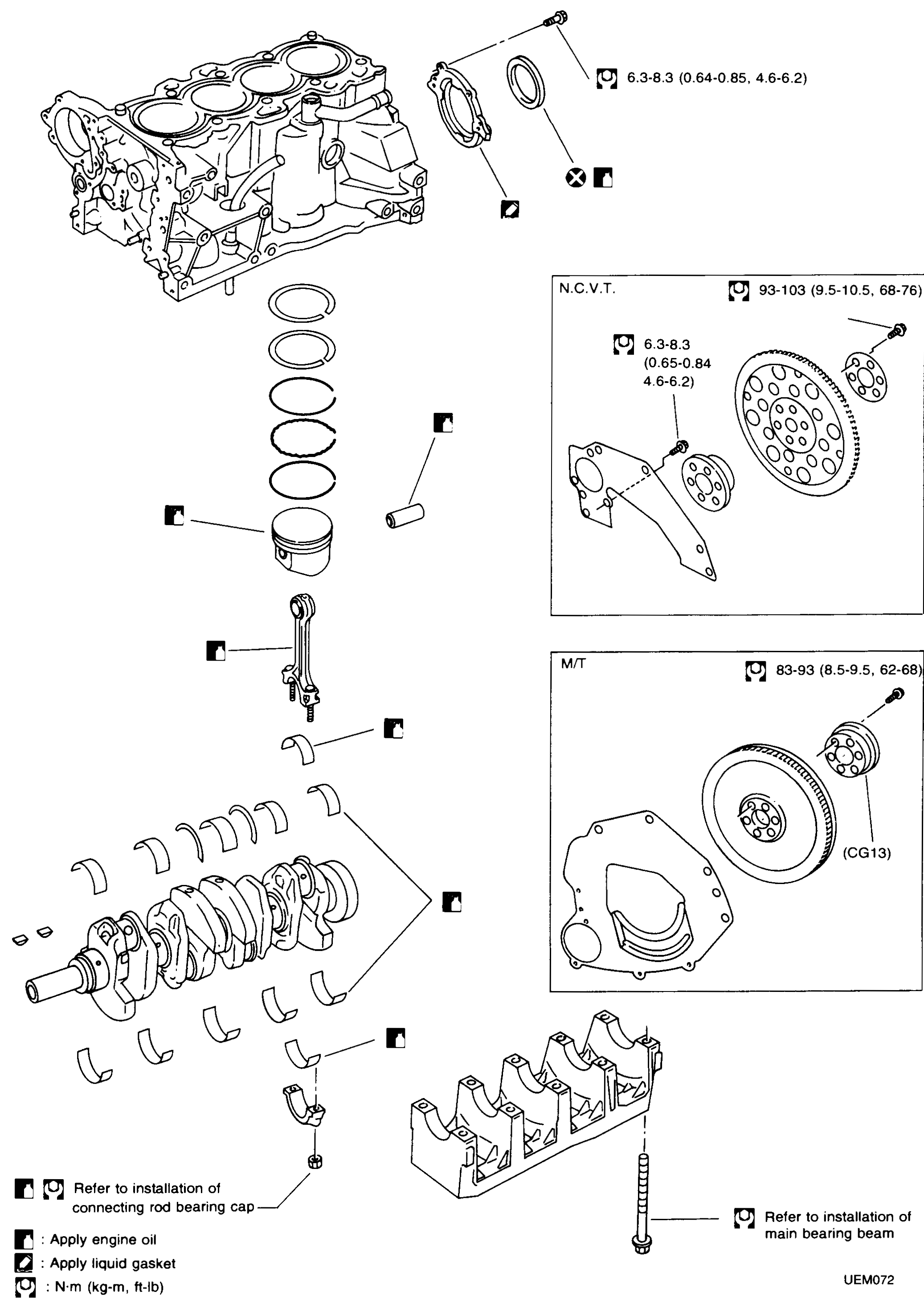
CYLINDER BLOCK — Exploded View
EM-43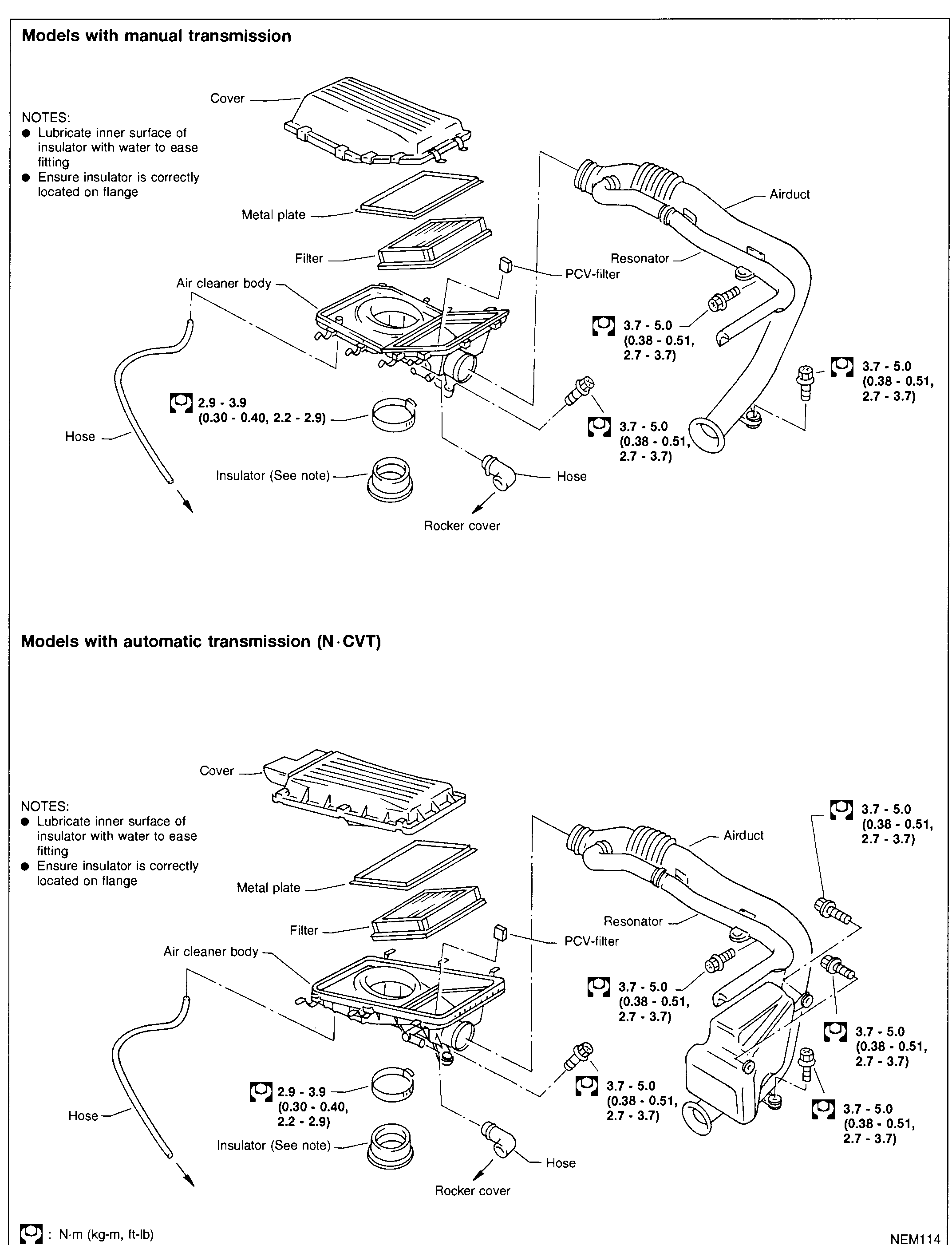
OUTER COMPONENT PARTS — Air Cleaner (Supplement-IV)
EM-4002Two stacked air-cleaner exploded views on one page. Top (Models with manual transmission): rectangular air-cleaner housing with separate cover, metal plate, filter element seated in cleaner body, PCV-filter; airduct connects to a resonator and ducting to the throttle body; insulator rubber boot mounts cleaner body to the rocker cover via a hose. Torque callouts: 2.9-3.9 N·m on the rocker-cover-stub clamp / 3.7-5.0 N·m on the airduct retainer bolts (three positions). Bottom (Models with automatic transmission, N·CVT): the same components in a wider housing with a different resonator volume; identical torque callouts plus one additional 3.7-5.0 N·m retainer on the auxiliary mounting tab.
OUTER COMPONENT PARTS — Air Cleaner (Supplement-IV)
EM-4002Two stacked air-cleaner exploded views on one page. Top (Models with manual transmission): rectangular air-cleaner housing with separate cover, metal plate, filter element seated in cleaner body, PCV-filter; airduct connects to a resonator and ducting to the throttle body; insulator rubber boot mounts cleaner body to the rocker cover via a hose. Torque callouts: 2.9-3.9 N·m on the rocker-cover-stub clamp / 3.7-5.0 N·m on the airduct retainer bolts (three positions). Bottom (Models with automatic transmission, N·CVT): the same components in a wider housing with a different resonator volume; identical torque callouts plus one additional 3.7-5.0 N·m retainer on the auxiliary mounting tab.
OUTER COMPONENT PARTS (Supplement-V)
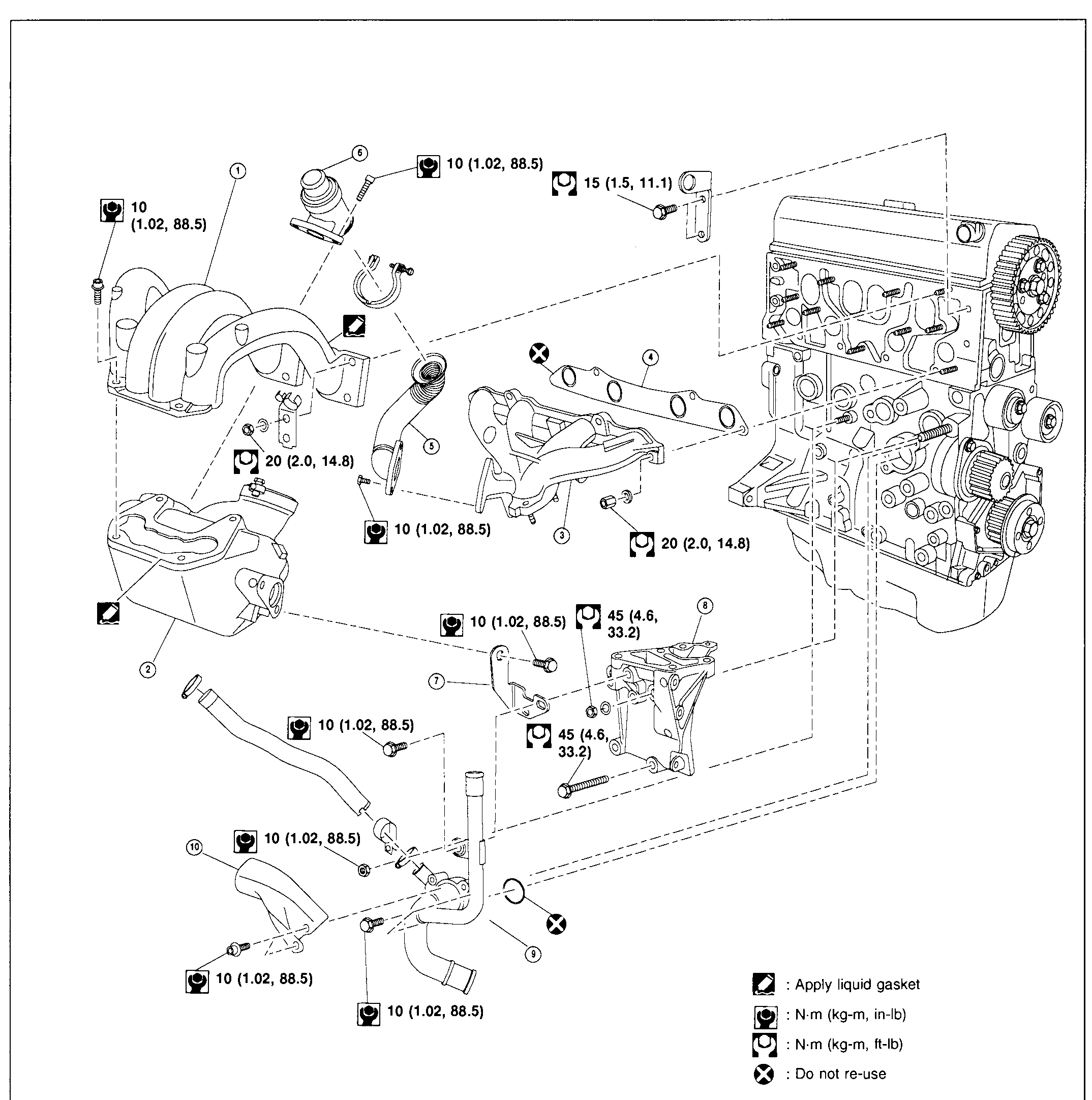
EM-5006Exploded view of the VJZ engine outer component parts. Shows the engine assembly (right) with intake manifold collector (2) and intake manifold (1) on the upper-left, exhaust manifold (3) and gasket (4) lower-middle, EGR valve (6) at top with EGR passage (5) connecting down to intake, bracket (7) below exhaust manifold, engine mounting support (8) to the right of bracket, water pipe assembly (9) along the bottom curving up to the engine, and heat shield (10) at lower-left covering the exhaust path. Torque callouts and a legend (Apply liquid gasket / N·m (kg-m, in-lb) / N·m (kg-m, ft-lb) / Do not re-use) appear at right.
OUTER COMPONENT PARTS (Cont'd) (Supplement-V)
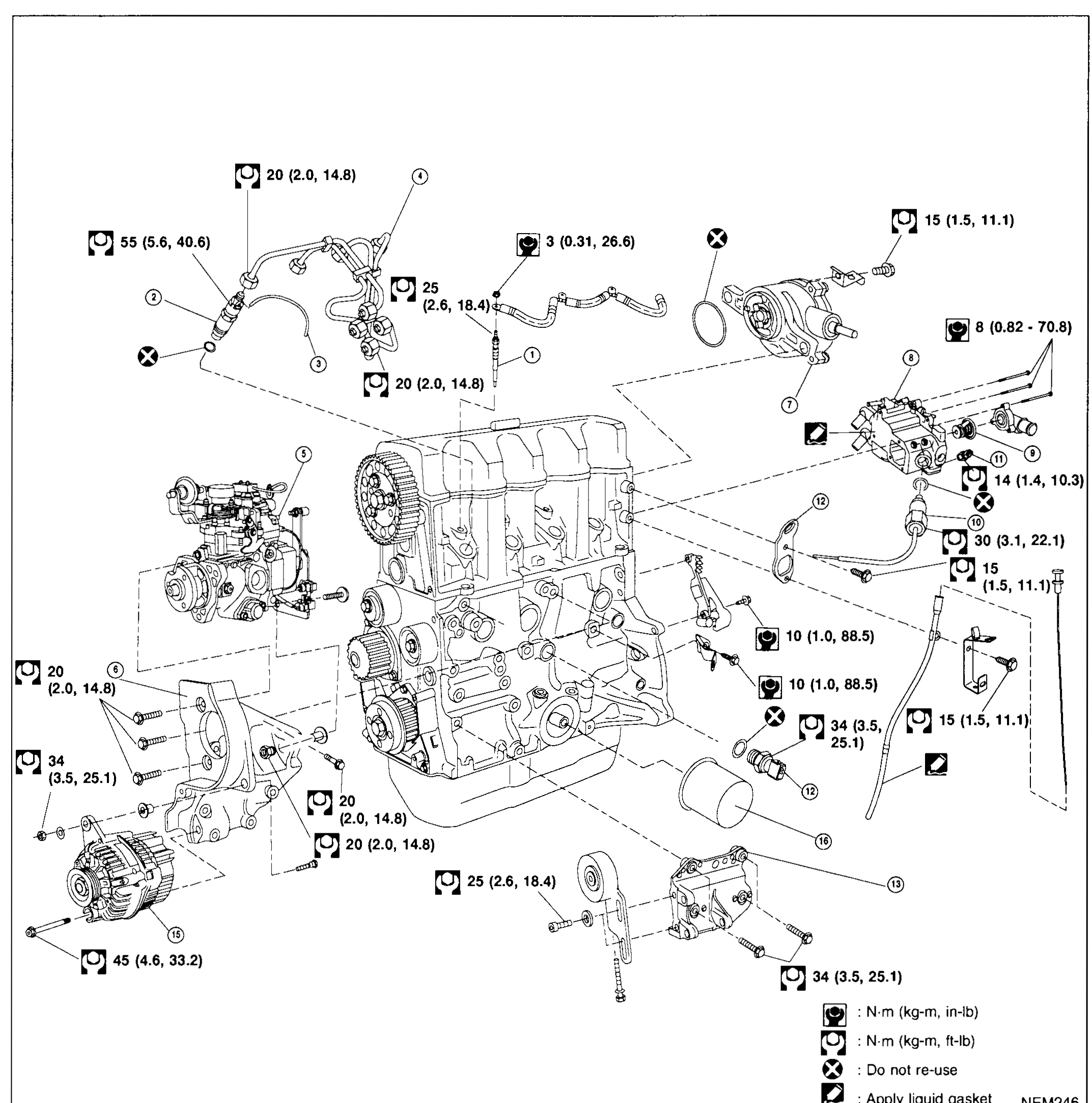
EM-5007Exploded view of the VJZ diesel engine outer accessories (front/timing-belt side and accessory drive). Visible components: glow plug (1) with feeder wire, injection nozzle (2) with spill hose (3), injection tube (4) running to injection pump (5) mounted on injection-pump bracket (6); vacuum pump (7) at top-right; thermostat housing (8) and thermostat (9); cold start device (10) on injection pump; water temperature sensor (11) on housing; engine slinger (12) at top-right; power steering oil pump bracket (13); oil pressure sensor (14); alternator (15) at lower-left on its bracket; oil filter (16) bottom-right. Torque callouts surround the assembly; legend at lower-right shows in-lb / ft-lb torque icons, Do-not-re-use symbol, and Apply-liquid-gasket symbol.
TIMING BELT — Cautions and Parts Diagram (Supplement-V)
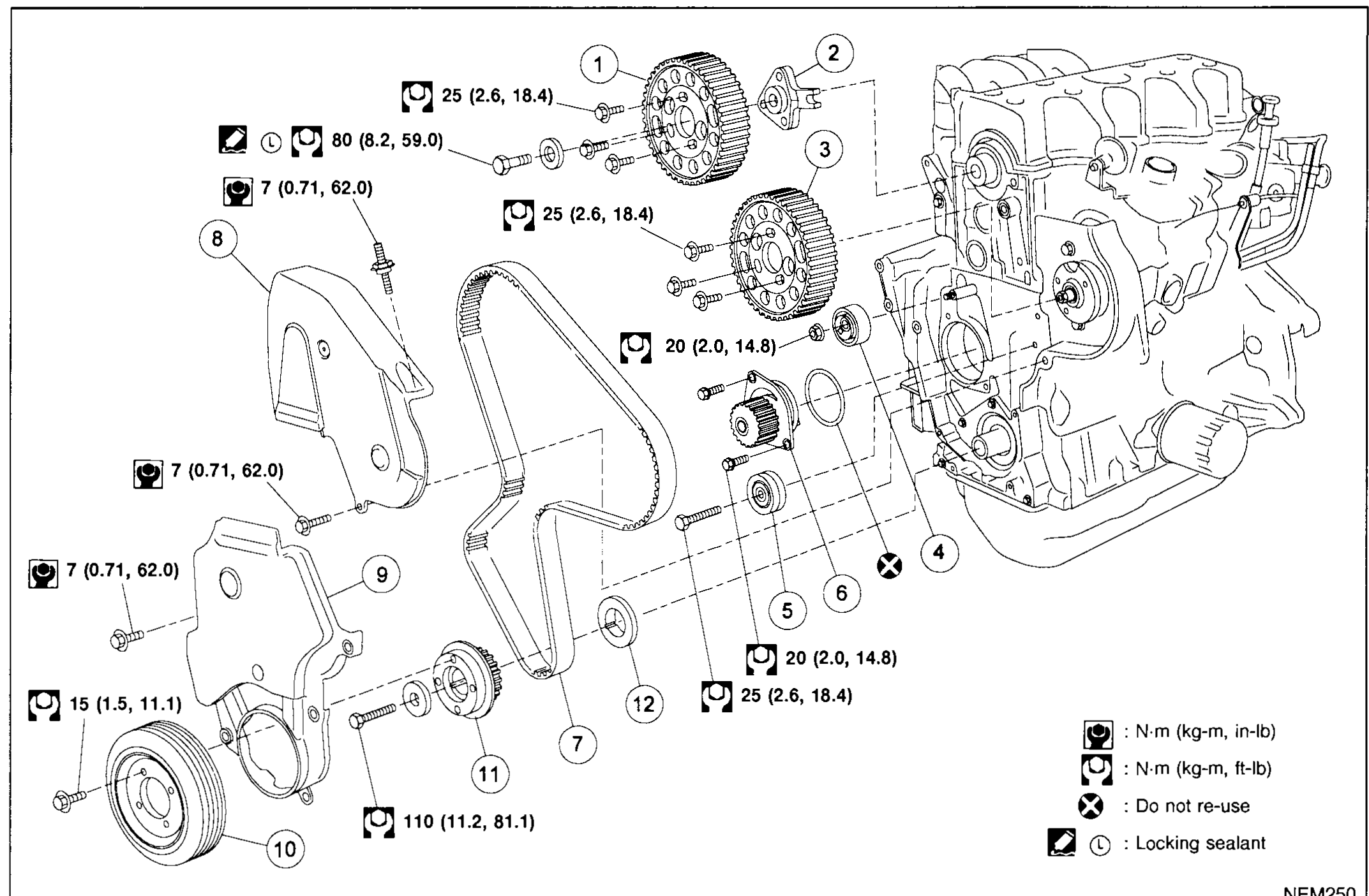
EM-5011Exploded view of the VJZ timing belt assembly. From left: crankshaft pulley (10) with crankshaft spacer (12) and crankshaft sprocket (11) on a stub of the crankshaft, lower timing belt cover (9) and upper timing belt cover (8), timing belt (7) routed up to the camshaft pulley (1) and hub (2) at top, injection pump pulley (3) to the right of camshaft, tensioner pulley (4) on the right-hand path, idler pulley (5) and water pump (6) on the lower-right. Torque callouts and a legend (N·m in-lb / N·m ft-lb / Do not re-use / Locking sealant) appear on the right side.
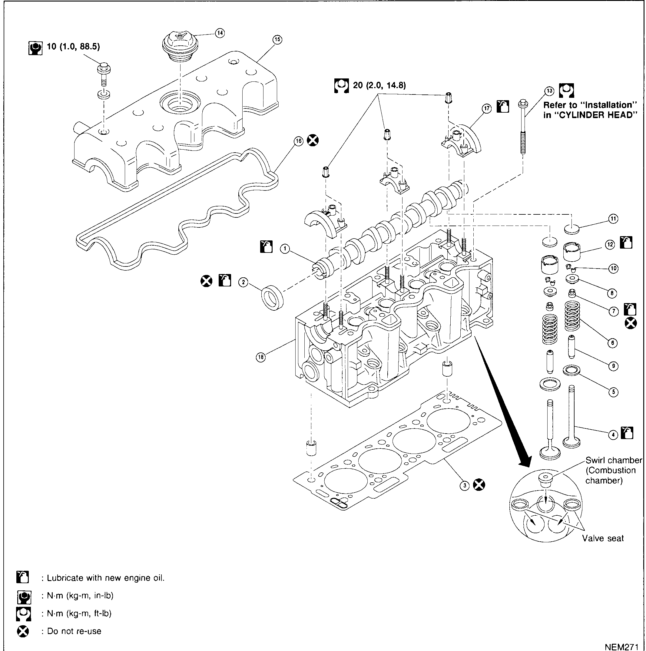
CYLINDER HEAD — Exploded View (Supplement-V)
EM-5019Full-page exploded view of the VJZ diesel cylinder head. Upper assembly: rocker cover (15) with oil filler cap (14) at top, rocker cover gasket (16) below — Do-not-re-use marker shown. Camshaft (1) sits in camshaft brackets (17) on top of cylinder head (18), with camshaft oil seal (2) on the front. Valve train (right): shim (11), valve lifter (12), valve cotter (10), spring retainer (8), valve spring (6) — Do-not-re-use marker, valve oil seal (7) — Lubricate marker, spring seat (5), valve guide (9), and valve (4) — Lubricate marker. Cylinder head gasket (3) — Do-not-re-use marker — sits between head and block (block not shown). Cylinder head bolt (13) callout points to a long stretch bolt with note 'Refer to "Installation" in "CYLINDER HEAD"'. Inset (lower-right): swirl-chamber / combustion-chamber detail with two valve seats and a glow-plug-like central element. Legend (lower-left): 'Lubricate with new engine oil' icon, in-lb torque icon, ft-lb torque icon, 'Do not re-use' icon.
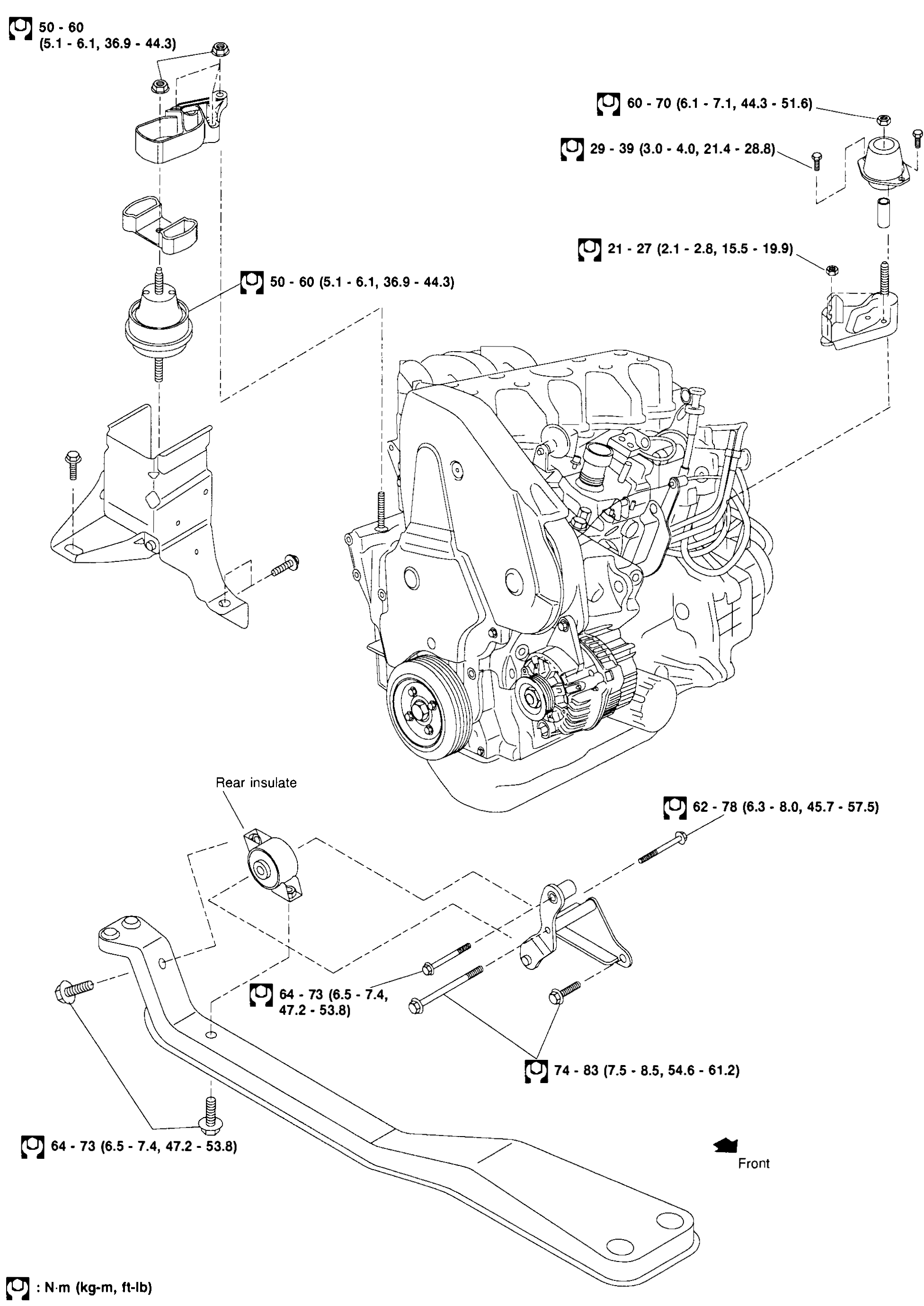
ENGINE REMOVAL — Engine Mounts Exploded View (Supplement-V)
EM-5031Exploded view of the VJZ engine and its mounting hardware. Centre: engine with timing belt cover and crankshaft pulley visible. Upper-left: LH (transaxle-side) engine mount bracket with bushing/insulator above it. Upper-right: RH (engine-side) mount bracket with bushing. Lower-centre: rear mount cross-member with 'Rear insulate' insulator bush above it, supported by the front cross-beam. 'Front' arrow indicates engine front direction (right). Torque callouts surround each mount. Legend (lower-left): N·m (kg-m, ft-lb) icon.
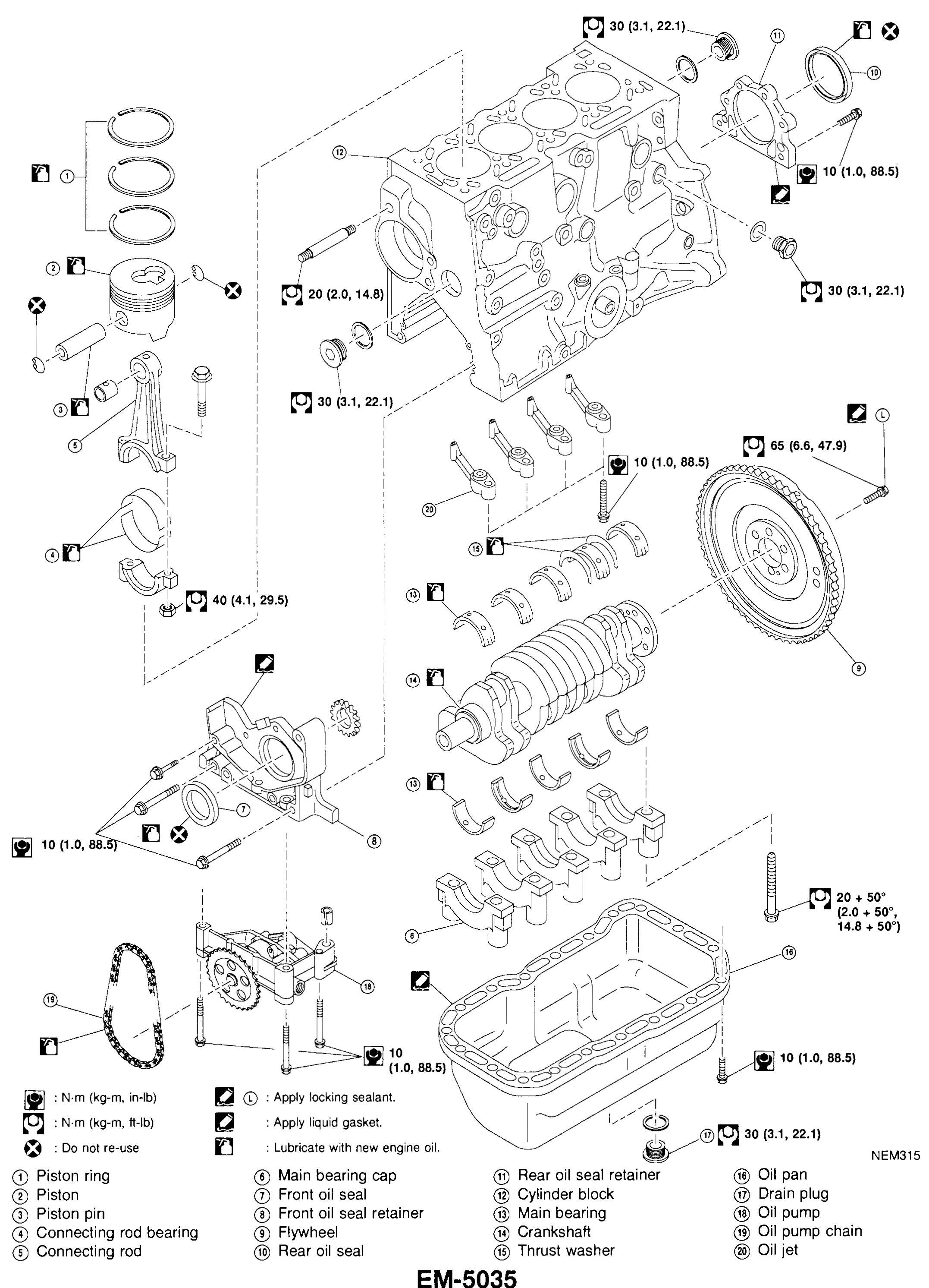
CYLINDER BLOCK — Exploded View (Supplement-V)
EM-5035Full-page exploded view of the VJZ diesel cylinder block. Top-left: piston rings (1), piston (2), piston pin (3), connecting rod (5) with conrod bearings (4) and cap. Center-left: front oil seal retainer (8) with front oil seal (7) and oil pump assembly (17) with oil pump chain (19). Upper-right: cylinder block (12) with bores. Inside-block items: main bearings (13) along the saddle, crankshaft (14) with thrust washer (15), main bearing caps (6). Right: flywheel (9) attached to crankshaft. Rear of block: rear oil seal retainer (11) with rear oil seal (10). Lower-centre: oil pan (16) with drain plug (18); oil jet (20) below cylinder bores. Torque, legend, and apply-marker icons surround the assembly.
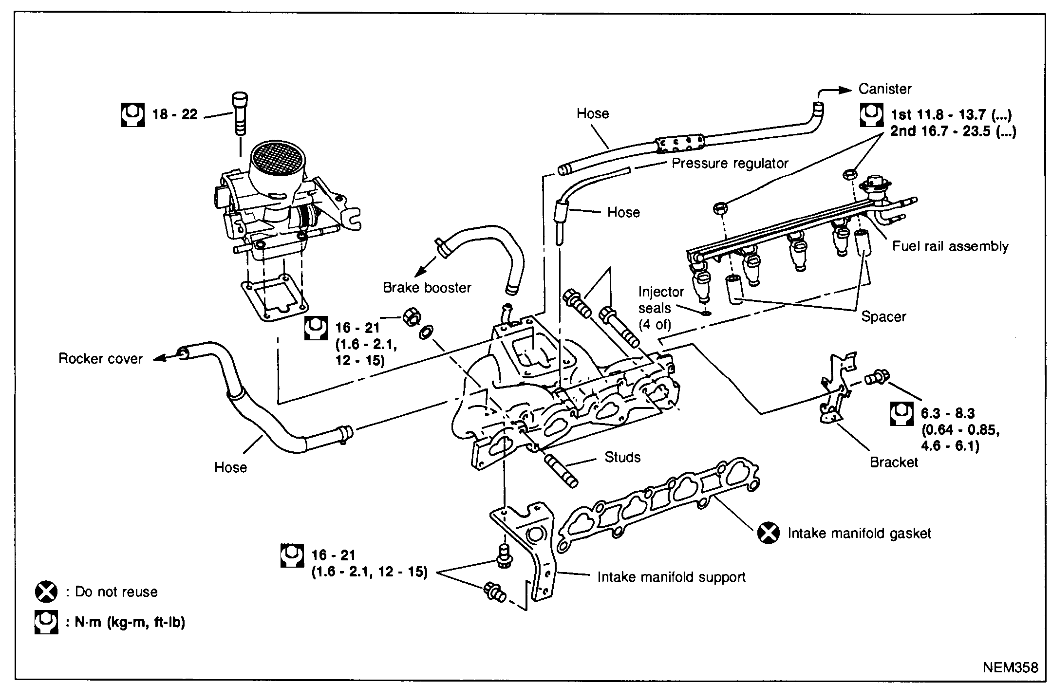
OUTER COMPONENT PARTS — Intake Manifold & Fuel System
EM-7002Exploded view of the intake manifold and fuel system assembly. Shows the throttle body/air-induction unit (top-left) bolting to the intake manifold (centre), with brake-booster hose, rocker-cover breather hose, fuel rail assembly with four injectors, pressure regulator with canister hose, injector seals (4 of), spacer, intake manifold support bracket, and intake manifold gasket. Torque callouts: 18-22 (throttle/manifold studs), 16-21 (1.6-2.1, 12-15) at the manifold-to-head and support, 6.3-8.3 (0.64-0.85, 4.6-6.1) at the bracket, and 1st 11.8-13.7 / 2nd 16.7-23.5 at the fuel rail nuts. Legends: filled-X = Do not reuse; wrench-icon = N·m (kg-m, ft-lb).
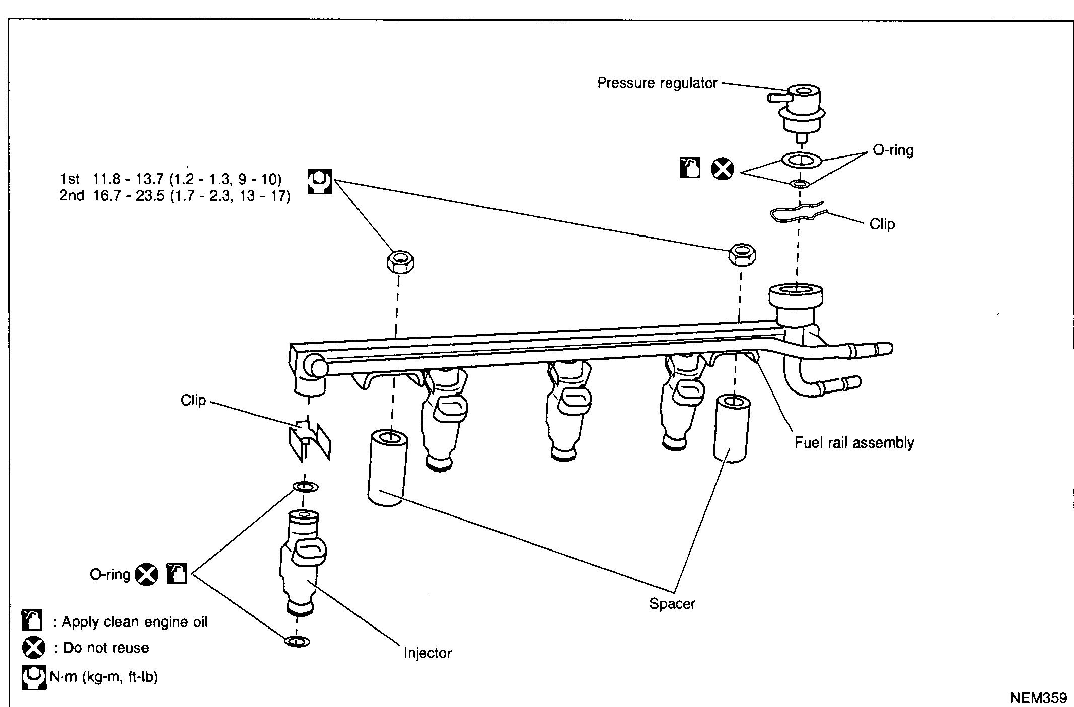
OUTER COMPONENT PARTS — Intake Manifold & Fuel System
EM-7002Exploded view of the fuel rail assembly. Shows the fuel rail with four injectors, spacers, O-rings, clips, and the pressure regulator. Torque callout for the fuel-rail mounting nuts: 1st 11.8-13.7 (1.2-1.3, 9-10) and 2nd 16.7-23.5 (1.7-2.3, 13-17) N·m (kg-m, ft-lb). Legends: oil-can icon = Apply clean engine oil; filled-X = Do not reuse; wrench-icon = N·m (kg-m, ft-lb).
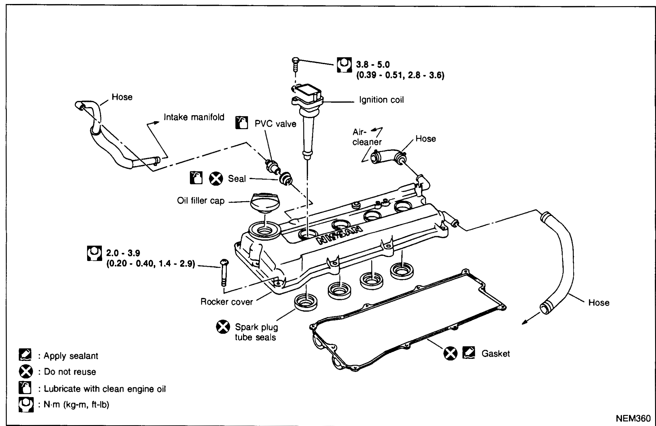
OUTER COMPONENT PARTS — Rocker Cover
EM-7003Exploded view of the rocker cover assembly. Shows ignition coil (top), PVC valve with seal, oil filler cap, hose to intake manifold, hose to air-cleaner, rocker cover, spark plug tube seals (four), and gasket. Torque callouts: 3.8 - 5.0 (0.39 - 0.51, 2.8 - 3.6) for the ignition coil hold-down, and 2.0 - 3.9 (0.20 - 0.40, 1.4 - 2.9) for the rocker cover bolts. Legends: sealant-icon = Apply sealant; filled-X = Do not reuse; oil-can icon = Lubricate with clean engine oil; wrench-icon = N·m (kg-m, ft-lb).
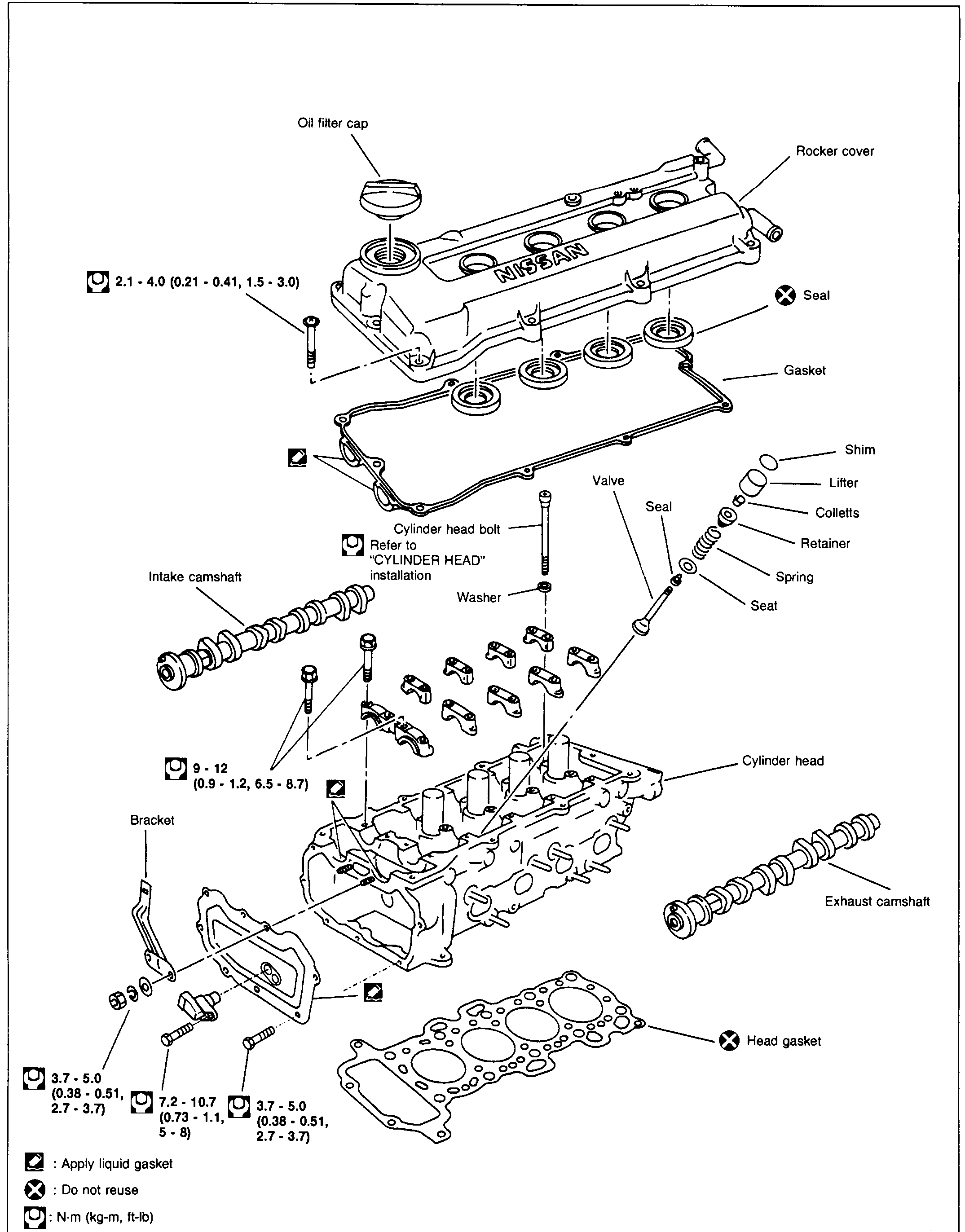
CYLINDER HEAD
EM-7014Full-page exploded view of the cylinder head assembly. Top: oil filler cap, rocker cover (NISSAN cast), spark-plug tube seals (4), gasket. Centre: intake camshaft (left), cylinder head bolts with washer, valve train components — valve, seal, spring, seat, retainer, colletts, lifter, shim. Lower: cylinder head, exhaust camshaft (right), head gasket. Lower-left: bracket with fasteners. Torque callouts: rocker cover bolt 2.1 - 4.0 (0.21 - 0.41, 1.5 - 3.0); cylinder head bolt 'Refer to CYLINDER HEAD installation'; cam-bracket / valve train fasteners 9 - 12 (0.9 - 1.2, 6.5 - 8.7); bracket fasteners 3.7 - 5.0 (0.38 - 0.51, 2.7 - 3.7) at two locations and 7.2 - 10.7 (0.73 - 1.1, 5 - 8) at the centre. Legend: liquid-gasket icon = Apply liquid gasket; filled-X = Do not reuse; wrench icon = N·m (kg-m, ft-lb).
Engine Lubrication & Cooling Systems
LC6 diagrams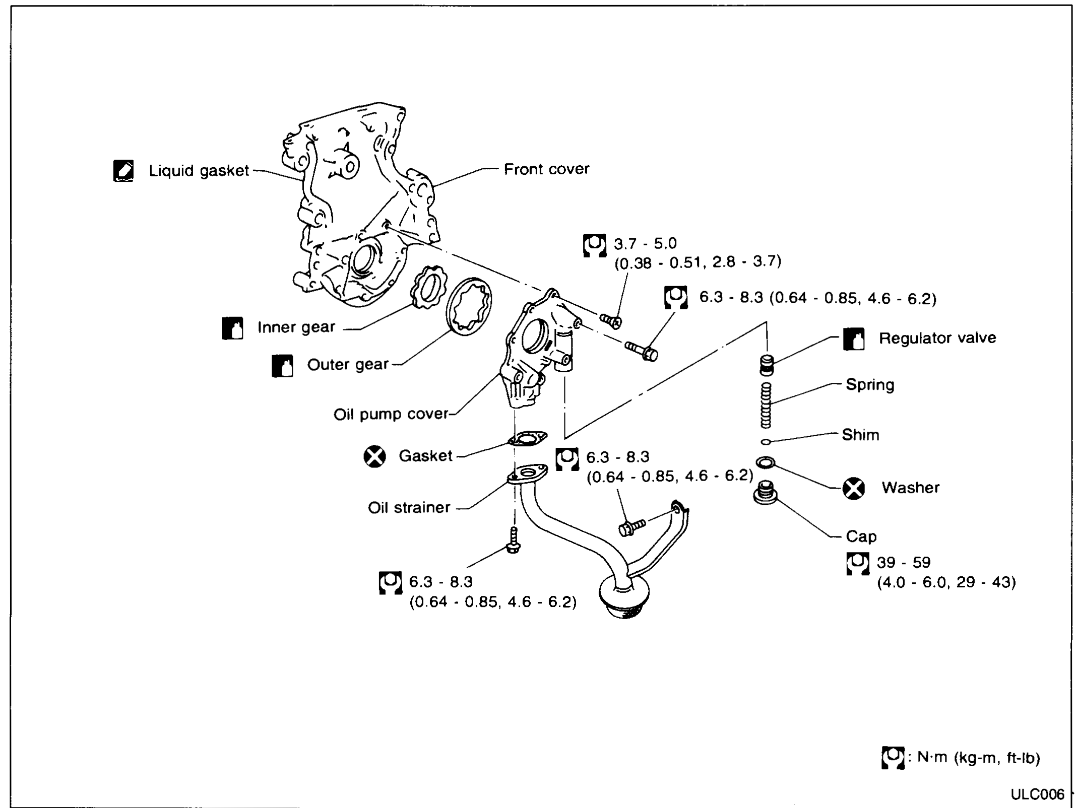
ENGINE LUBRICATION SYSTEM - Oil Pump
LC-6Exploded view of the oil pump assembly. Shows the front cover with liquid gasket application points, inner gear and outer gear seated inside the cover, oil pump cover with gasket and oil strainer, and the regulator valve column (regulator valve, spring, shim, washer, cap). Tightening-torque callouts in N·m (kg-m, ft-lb) are placed next to each fastener with the legend at bottom right.
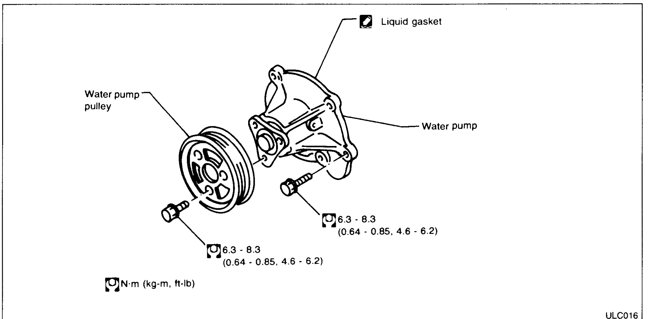
ENGINE COOLING SYSTEM - Water Pump
LC-10Exploded view of the water pump assembly. Water pump pulley (left, with V-grooves) bolted to the water pump body (centre), liquid gasket called out on the upper mating face of the pump. Two mounting bolts shown with tightening-torque callouts of 6.3 - 8.3 N·m (0.64 - 0.85 kg-m, 4.6 - 6.2 ft-lb). Legend N·m (kg-m, ft-lb) at lower left.
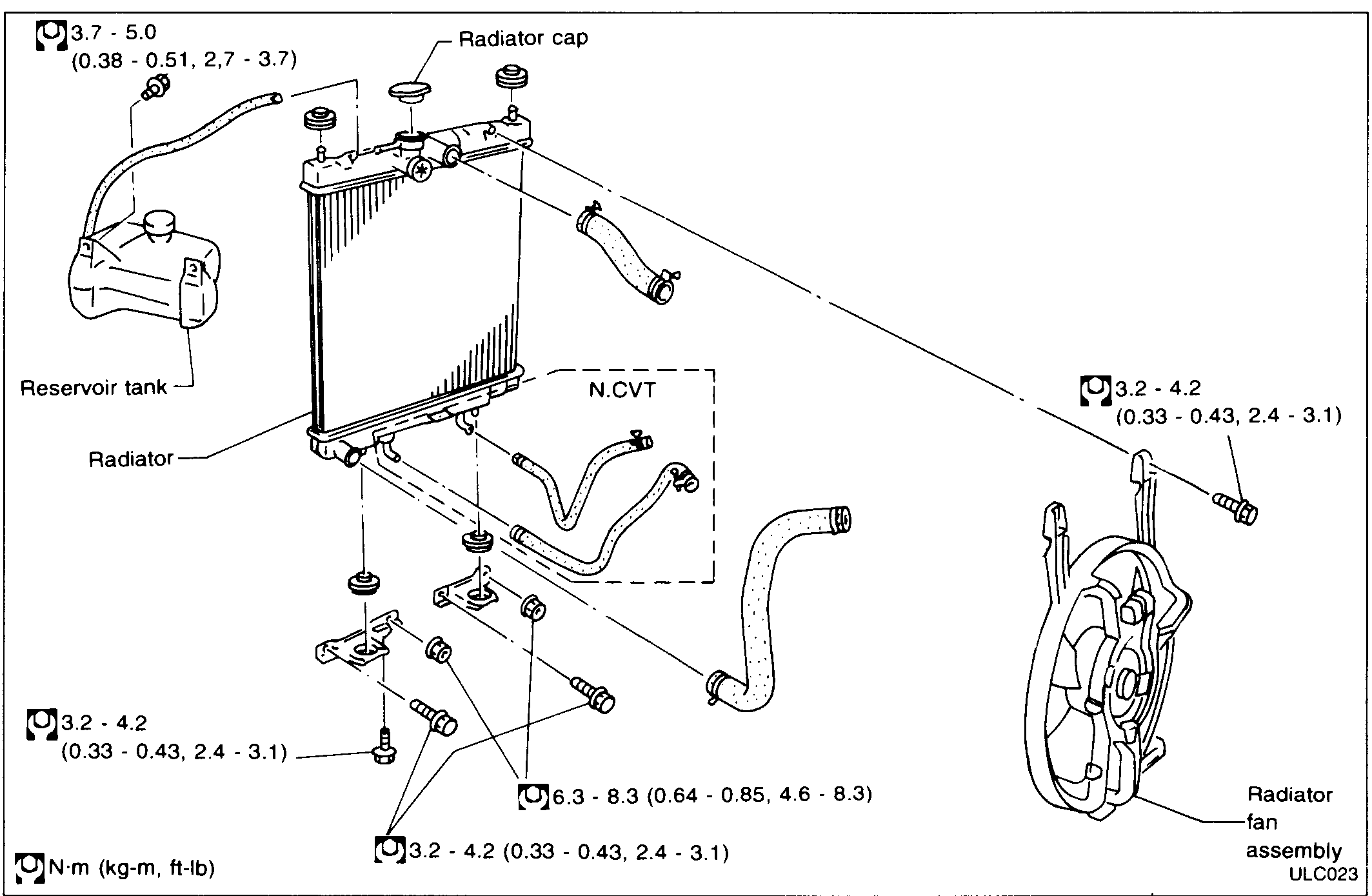
ENGINE COOLING SYSTEM - Thermostat Housing / Radiator / Electrical Cooling Fan
LC-12Exploded view of the radiator assembly with reservoir tank to the left, radiator core in centre, upper and lower coolant hoses, N.CVT (auto-transmission cooler line) hose loop shown inside a dashed box at lower centre, radiator fan assembly on the right. Mounting brackets, rubber bushes and bolts are shown with multiple tightening-torque callouts in N·m (kg-m, ft-lb).
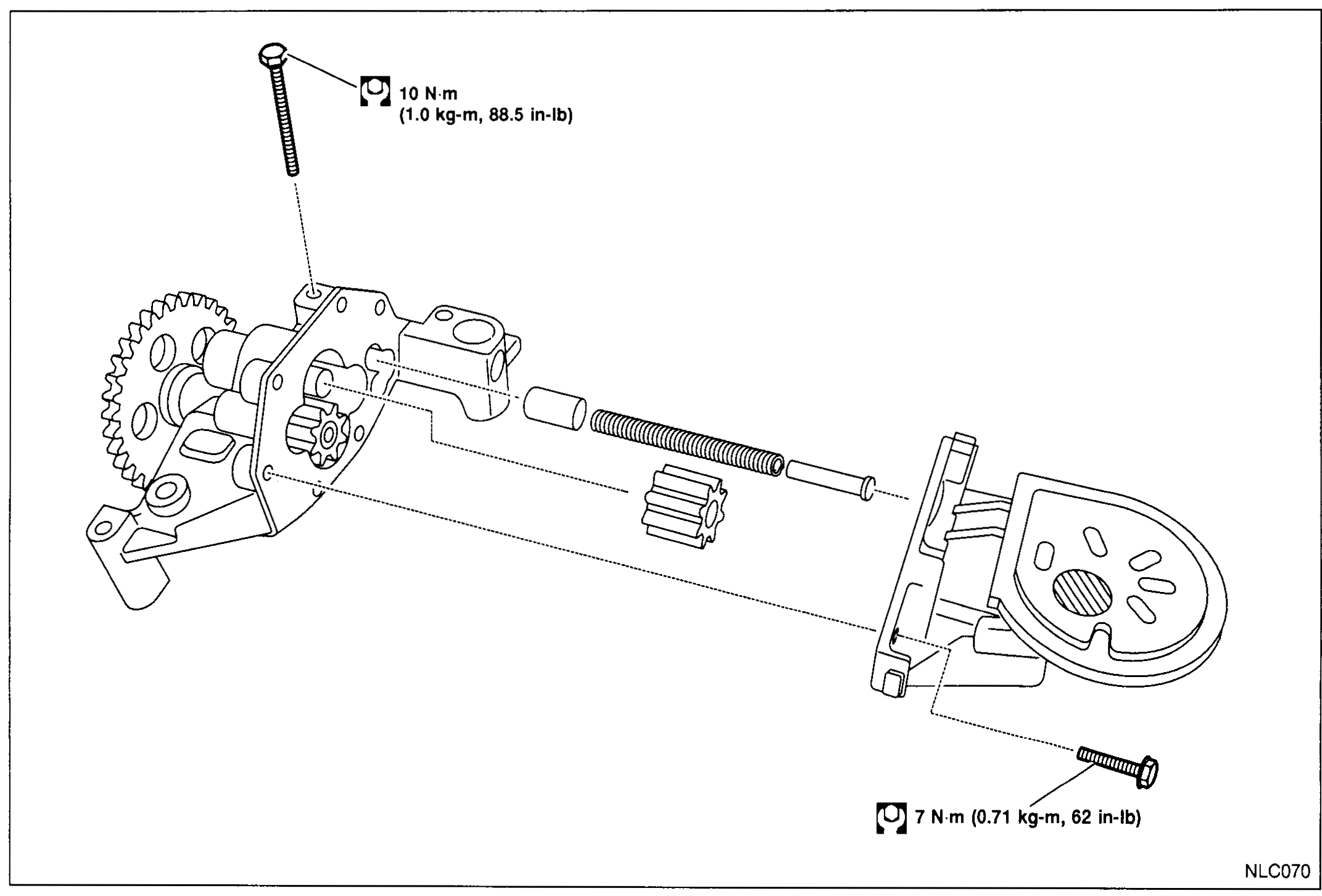
ENGINE LUBRICATION SYSTEM - Oil Pump (Cont'd) - Disassembly and Assembly
LC-5004Exploded view of the oil pump for the VJZ engine. Shows pump body with drive sprocket (large gear) and driven gear, an internal pinion, a long pressure-regulator valve assembly (plunger + spring), and the pump cover with an oval/kidney-shaped relief / strainer pickup port. Long bolt at upper left with torque callout '10 N·m (1.0 kg-m, 88.5 in-lb)'. Cover bolt at lower right with torque callout '7 N·m (0.71 kg-m, 62 in-lb)'.
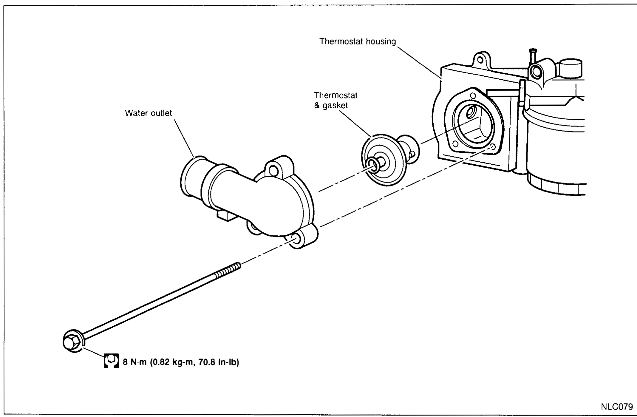
ENGINE COOLING SYSTEM - Thermostat - Removal and Installation
LC-5009Exploded view of thermostat installation: water outlet pipe (left) bolts via a long-shank fastener to the thermostat housing (right) on the engine, with the thermostat & gasket sandwiched between them. Long bolt at lower left with torque callout '8 N·m (0.82 kg-m, 70.8 in-lb)'.
ENGINE COOLING SYSTEM - Radiator (VJZ)
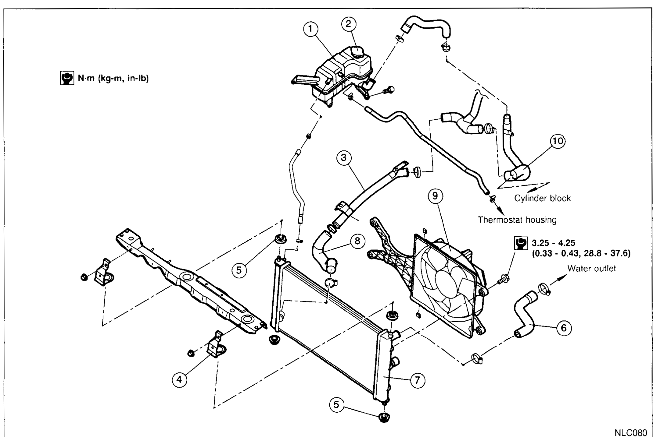
LC-5010Exploded view of the VJZ radiator system. Numbered callouts: (1) Coolant reservoir, (2) Coolant reservoir cap, (3) Lower radiator tube, (4) Mounting bracket, (5) Mounting rubber, (6) Upper radiator hose, (7) Radiator, (8) Lower radiator hose, (9) Cooling fan, (10) Inlet tube. Cylinder block, thermostat housing and water outlet are labeled at the engine side; fastener torque 3.25 - 4.25 N·m (0.33 - 0.43, 28.8 - 37.6).
Engine Control, Fuel & Exhaust System
FE2 diagrams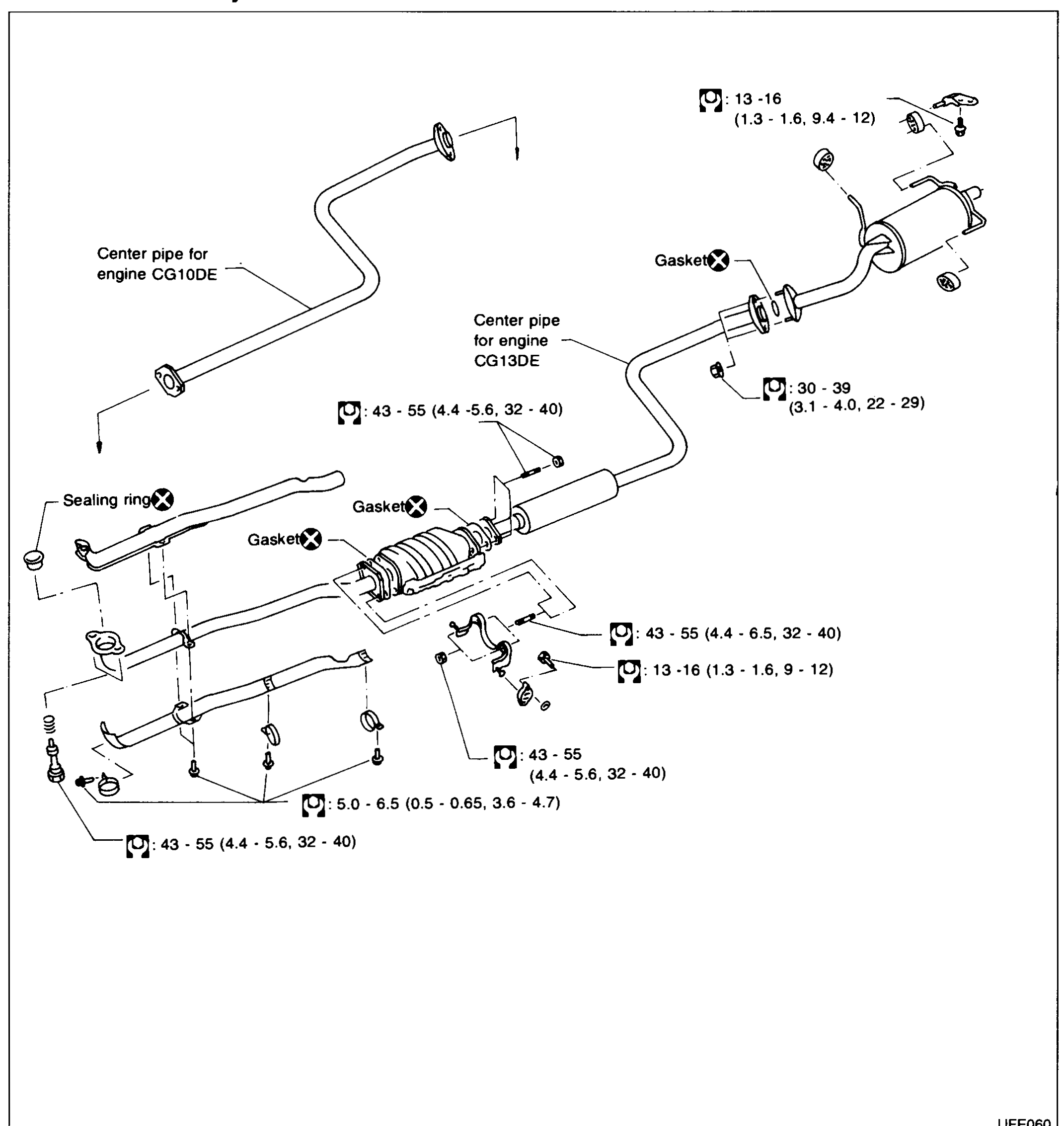
EXHAUST SYSTEM
FE-10Exploded view of the K11 exhaust system. Left/upper shows the front pipe with a sealing ring and gasket connecting to the catalytic converter / centre section. Two centre-pipe variants are called out: 'Center pipe for engine CG10DE' (upper) and 'Center pipe for engine CG13DE' (lower). Centre section continues to the rear muffler (right) with mounting hangers and gaskets at each tube junction. Torque values in N·m (kg-m, ft-lb) are stamped beside each fastener.
EXHAUST SYSTEM (VJZ — Diesel engine models)
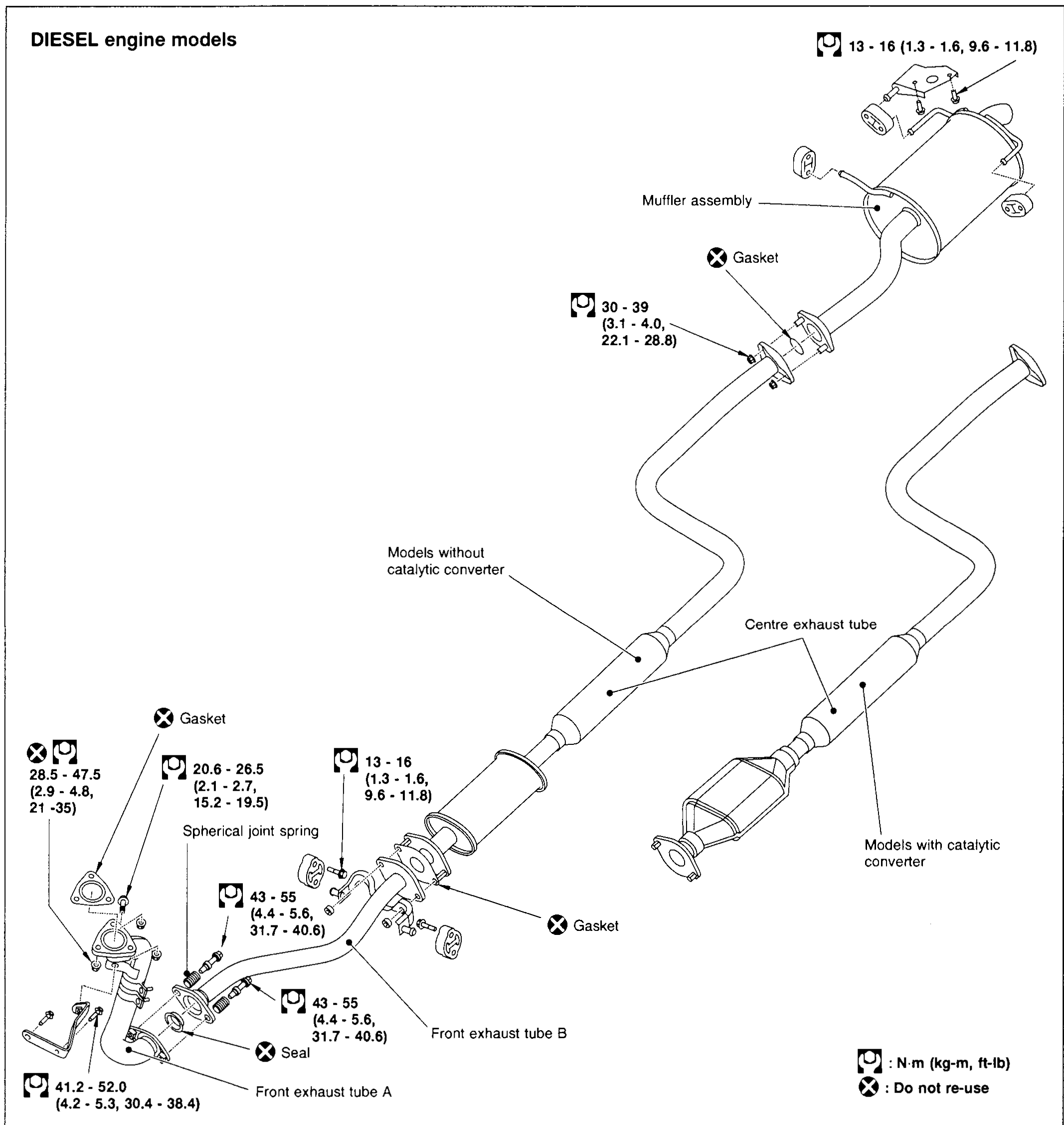
FE-5004Exploded view of the diesel-engine exhaust system. Lower-left shows 'Front exhaust tube A' joining at the manifold flange with a gasket and the spherical joint spring. 'Front exhaust tube B' connects rearward via a flanged joint with another gasket and seal. Centre shows two centre-pipe variants labelled 'Models without catalytic converter' (upper) and 'Models with catalytic converter' (lower with cat). 'Centre exhaust tube' is called out at right. The muffler assembly is at top-right with hanger and gasket. Torque values in N·m (kg-m, ft-lb) and 'Do not re-use' symbols are stamped beside each fastener.
Clutch
CL4 diagrams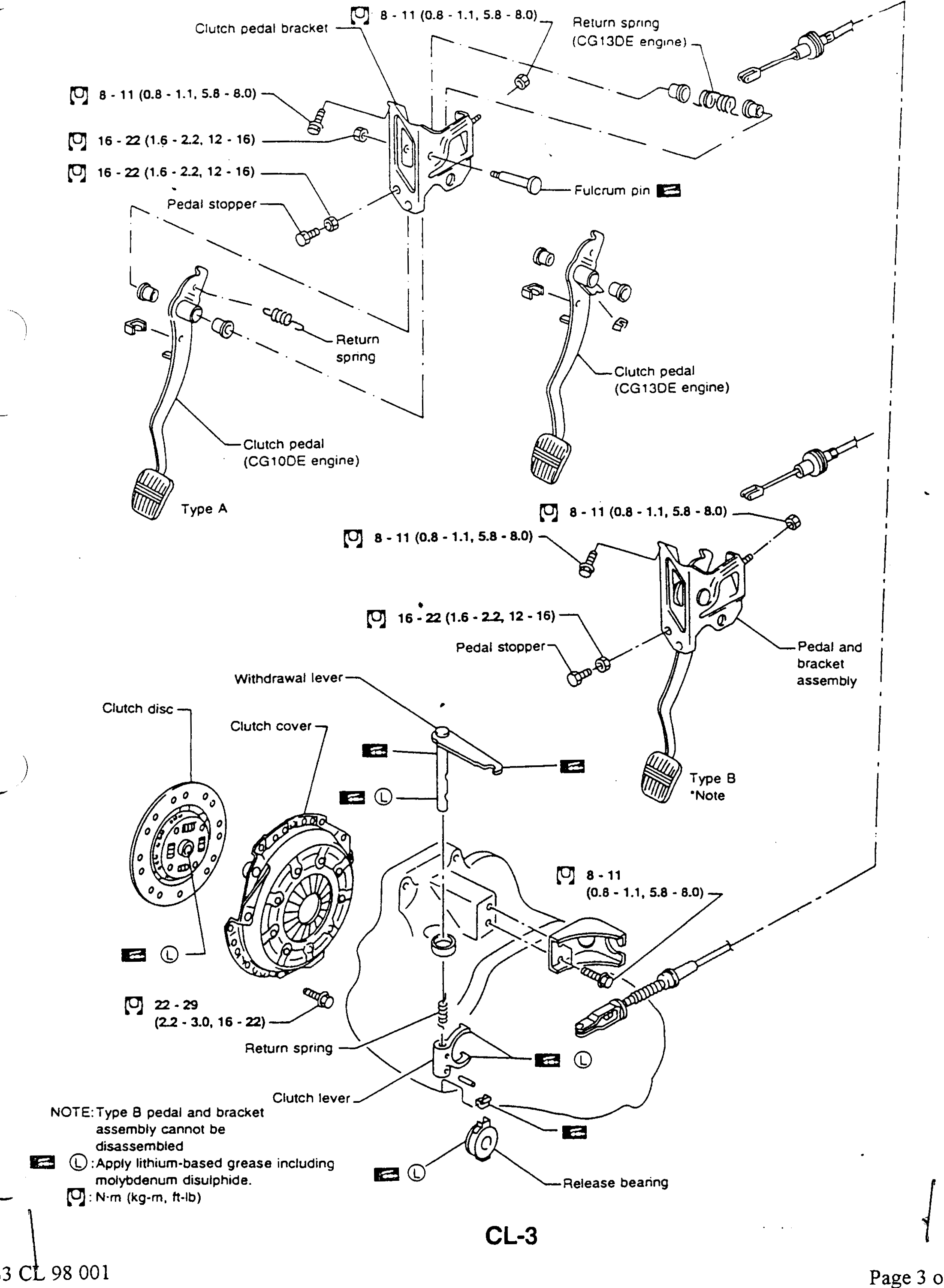
CLUTCH SYSTEM
CL-3Exploded view of the K11 clutch system in two pedal variants (Type A and Type B). Upper section shows Type A: clutch pedal bracket, return spring (CG13DE engine), fulcrum pin, pedal stopper, return spring, clutch pedal (CG10DE engine) and clutch pedal (CG13DE engine). Middle section shows Type B with a pedal-and-bracket assembly that cannot be disassembled. Lower section shows the clutch disc, clutch cover, withdrawal lever, return spring, clutch lever, and release bearing. Torque values are called out at fasteners; grease application points are marked with L symbols. Footer indicates 'Page 3 of 4' with revision tag 'B3 CL 98 001'.
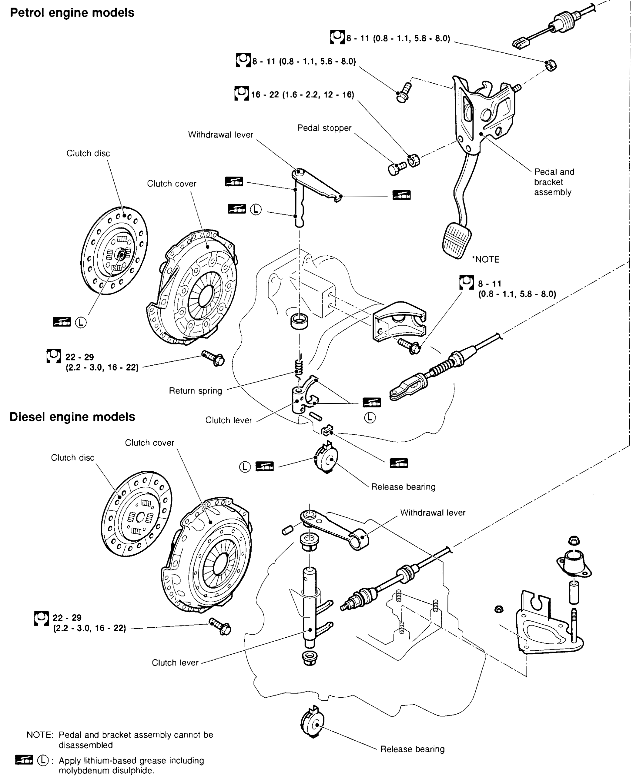
CLUTCH SYSTEM
CL-5003Two stacked exploded views of the clutch system. Upper view 'Petrol engine models' shows the clutch disc, clutch cover, withdrawal lever, pedal stopper, pedal-and-bracket assembly (note: cannot be disassembled), clutch lever, return spring, and release bearing. Lower view 'Diesel engine models' shows the clutch disc, clutch cover, withdrawal lever, clutch lever, and release bearing for the diesel-engine variant. Torque values and grease-application markers (L symbols) are placed next to fasteners and pivot points.
CLUTCH SYSTEM
CL-5003Two stacked exploded views of the clutch system. Upper view 'Petrol engine models' shows the clutch disc, clutch cover, withdrawal lever, pedal stopper, pedal-and-bracket assembly (note: cannot be disassembled), clutch lever, return spring, and release bearing. Lower view 'Diesel engine models' shows the clutch disc, clutch cover, withdrawal lever, clutch lever, and release bearing for the diesel-engine variant. Torque values and grease-application markers (L symbols) are placed next to fasteners and pivot points.
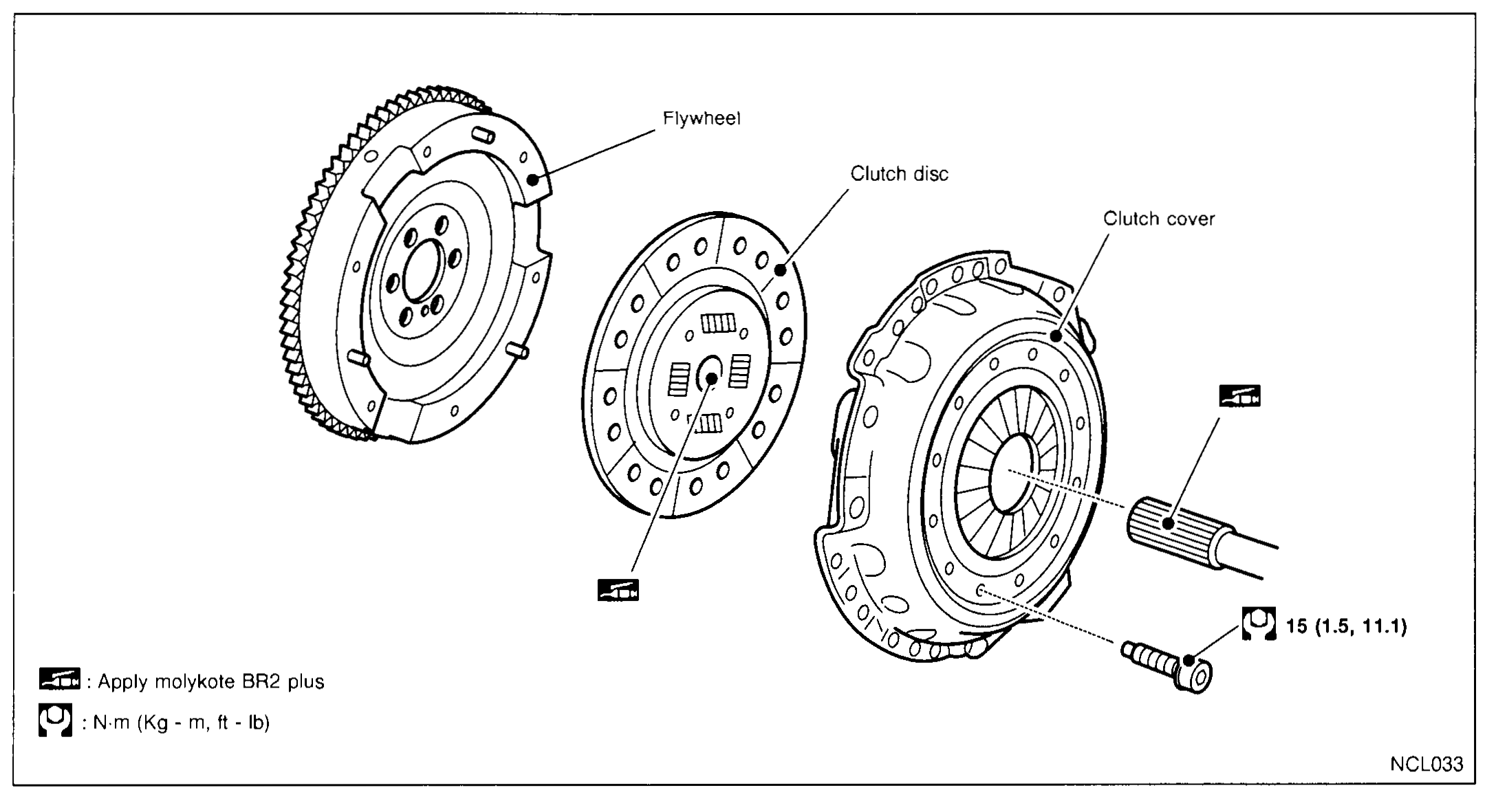
CLUTCH DISC AND CLUTCH COVER
CL-5006Exploded view of the clutch disc and clutch cover assembly (Supplement-V variant). Left to right: flywheel (with ring gear), clutch disc, clutch cover, and the transmission input shaft. Torque callout on the clutch cover bolt: 15 (1.5, 11.1) N·m (kg-m, ft-lb). Grease-application markers indicate 'Apply molykote BR2 plus' on the input-shaft splines and clutch disc hub. Legend at bottom-left: marker = Apply molykote BR2 plus; torque marker = N·m (kg-m, ft-lb).
Manual Transmission
MT11 diagrams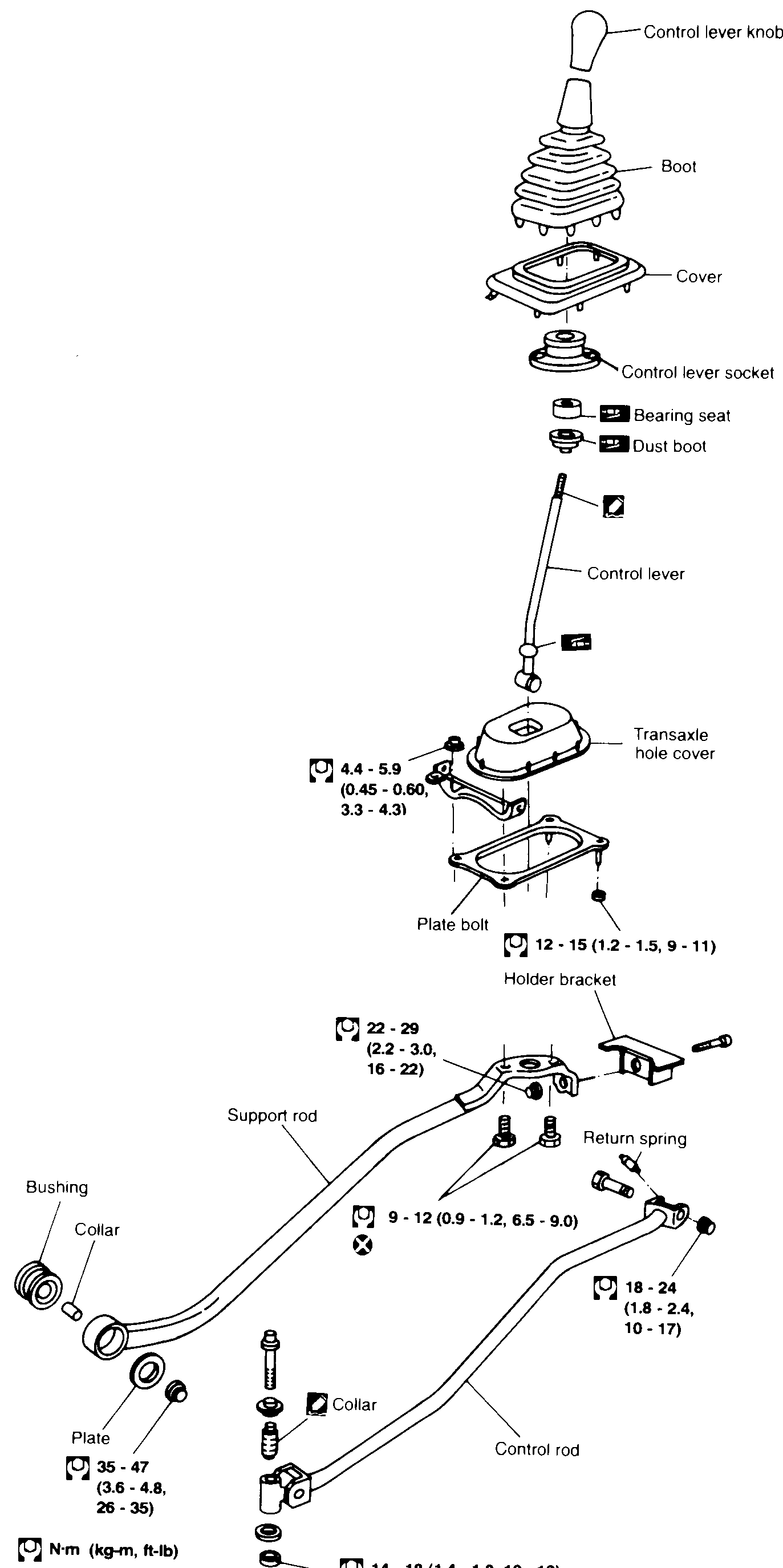
TRANSAXLE GEAR CONTROL
MT-8Full-page exploded view of the transaxle gear-control linkage. Top stack (vertical): Control lever knob, Boot, Cover, Control lever socket, Bearing seat, Dust boot, Control lever, Transaxle hole cover, Plate bolt, Holder bracket. Below: Support rod (with Bushing, Collar, Plate at its outer end) on the left and Control rod (with Collar, Return spring) on the right, mounting onto the transaxle. Torque values are called out next to each fastener with the legend N·m (kg-m, ft-lb) and an X (do-not-reuse) marker.
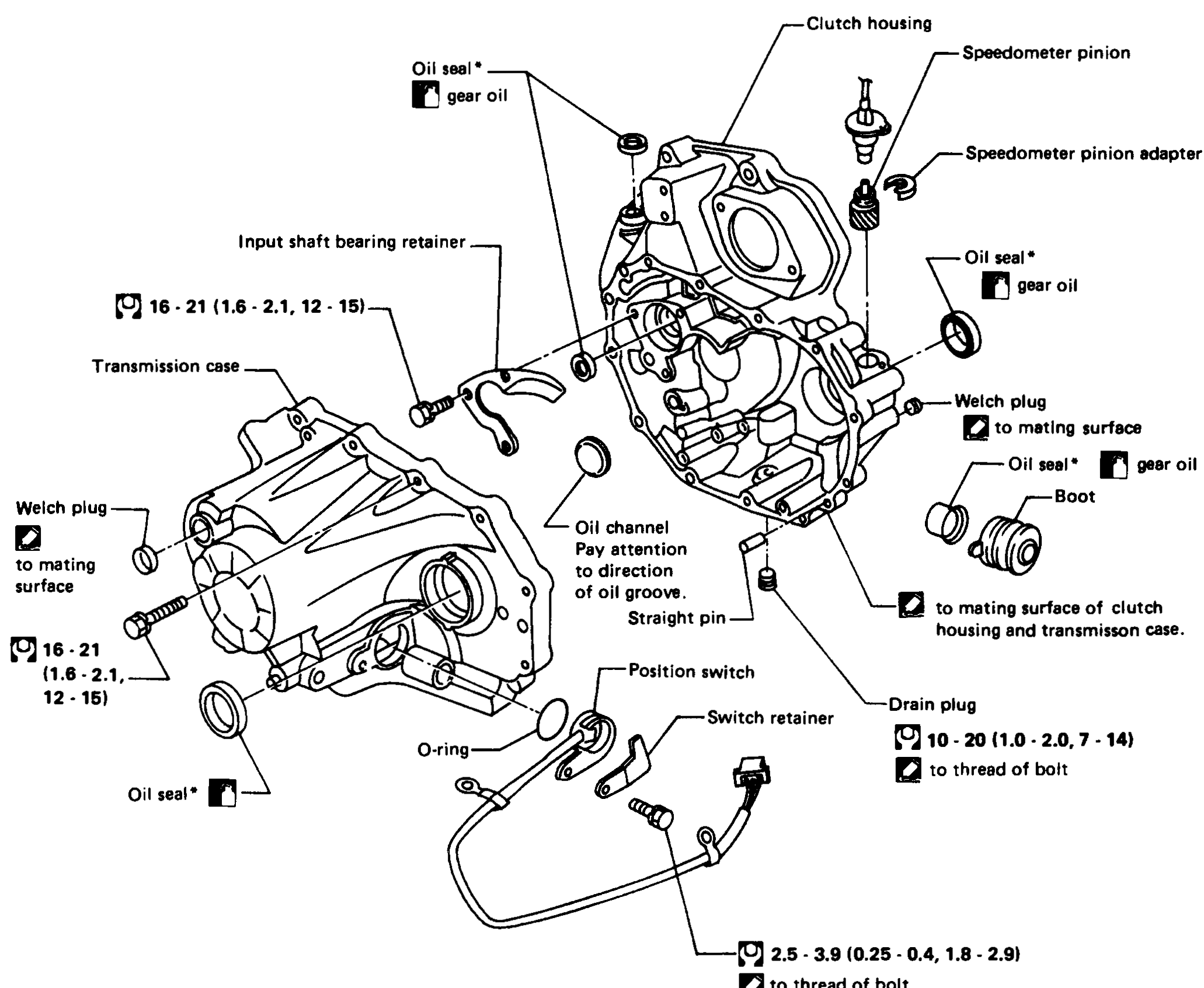
MAJOR OVERHAUL — Case components (RS5F41A)
MT-9Exploded view of the RS5F41A transaxle case components. Left side shows the Transmission case with Welch plug, Oil seal*, and Input shaft bearing retainer; an O-ring, Position switch with Switch retainer, and Drain plug at the bottom. Right side shows the Clutch housing with Speedometer pinion, Speedometer pinion adapter, Oil seal*, Welch plug, and Boot. Centre callouts: Oil channel — pay attention to direction of oil groove; Straight pin. Torque values: 16 - 21 (1.6 - 2.1, 12 - 15) for input shaft bearing retainer bolts and a transmission-case bolt; 10 - 20 (1.0 - 2.0, 7 - 14) for drain plug; 2.5 - 3.9 (0.25 - 0.4, 1.8 - 2.9) for switch retainer.
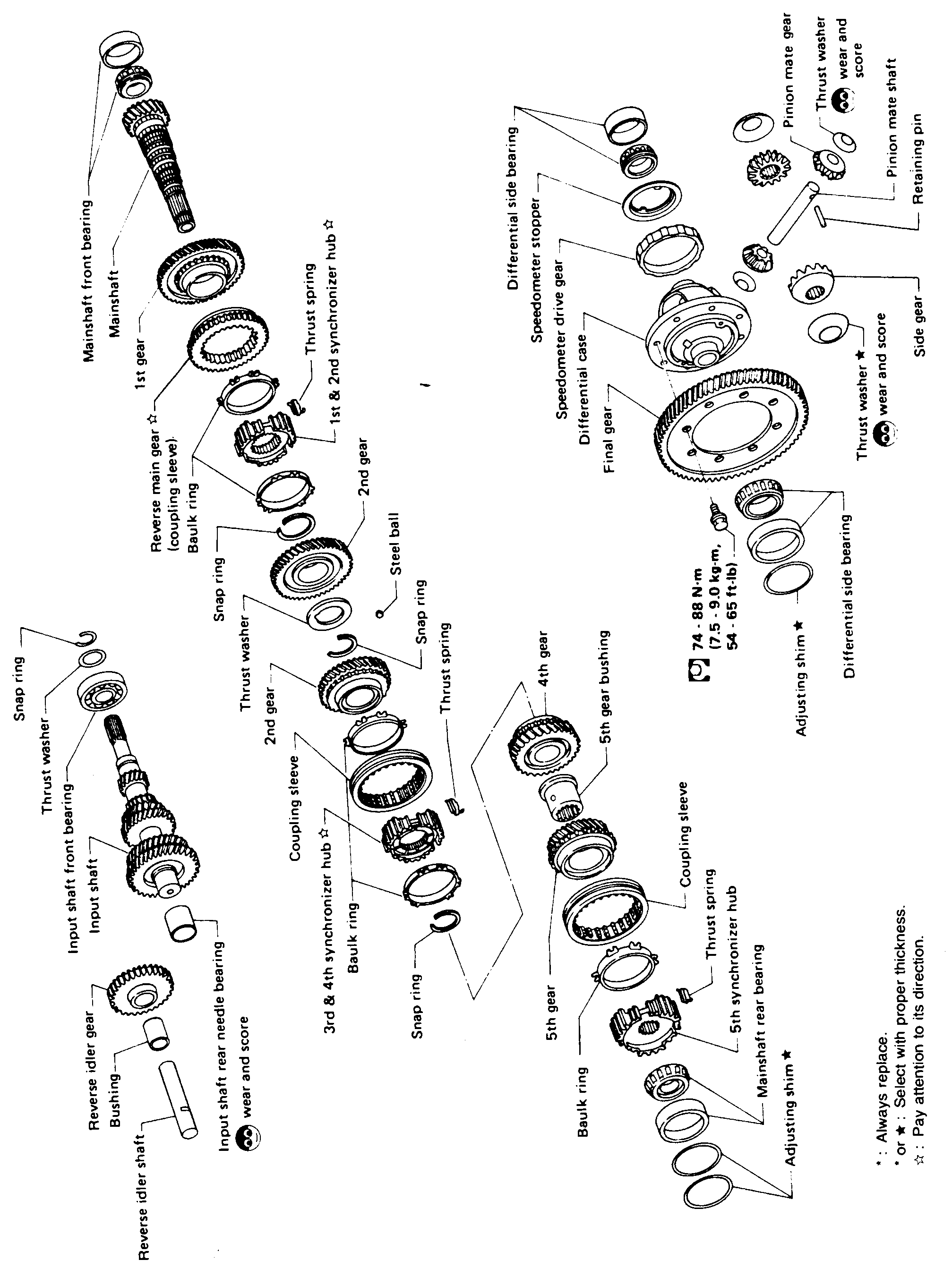
MAJOR OVERHAUL — Gear Components (RS5F41A)
MT-10Full-page exploded view of the RS5F41A transaxle gear components. Top-left: mainshaft assembly with mainshaft front bearing, 1st gear, reverse main gear (coupling sleeve), baulk ring, 1st & 2nd synchronizer hub, thrust spring, 2nd gear, snap ring, steel ball, thrust washer, snap ring. Middle: input shaft assembly with snap ring, thrust washer, input shaft front bearing, input shaft, coupling sleeve, 3rd & 4th synchronizer hub, baulk ring, 4th gear, thrust spring, 5th gear bushing. Bottom: 5th-gear region with 5th gear, coupling sleeve, thrust spring, 5th synchronizer hub, mainshaft rear bearing, adjusting shim, baulk ring, snap ring. Lower-left: reverse idler gear, bushing, reverse idler shaft, input shaft rear needle bearing. Right side: final-drive / differential assembly with differential side bearing (two), differential case, final gear, speedometer drive gear, speedometer stopper, differential side bearing, adjusting shim, side gear, thrust washer, pinion mate gear, pinion mate shaft, retaining pin. Torque callout on the differential side-bearing area: 74 - 88 N·m (7.5 - 9.0 kg-m, 54 - 65 ft-lb). Legend at lower-right: * Always replace; • or ★ Select with proper thickness; ☆ Pay attention to its direction; ◐ wear and score.
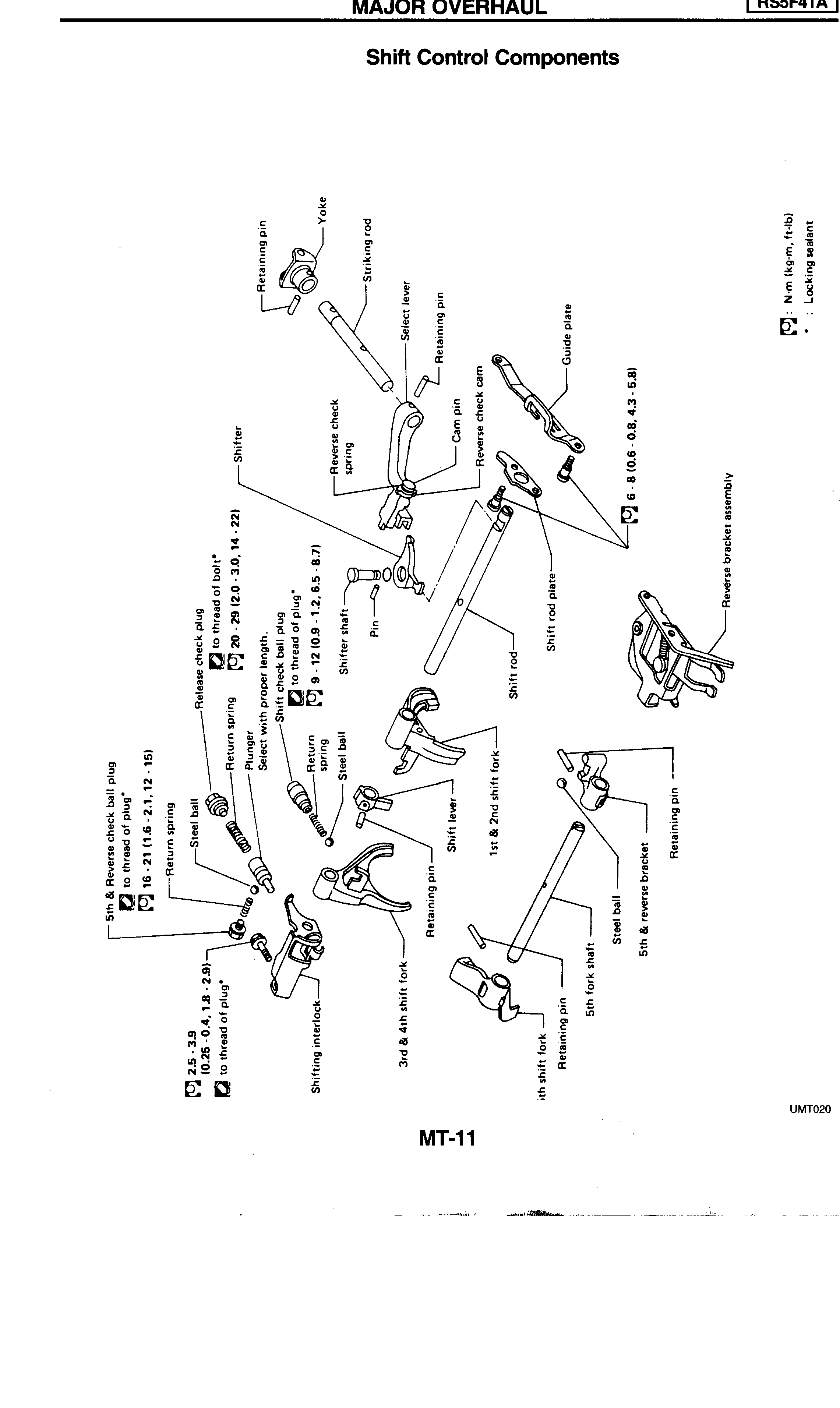
MAJOR OVERHAUL — Shift Control Components (RS5F41A)
MT-11Full-page exploded view of the RS5F41A shift-control components. Top: yoke with retaining pin, striking rod, select lever, reverse check cam, reverse check spring, cam pin, retaining pin, guide plate, shift rod plate, reverse bracket assembly. Middle: shifter, shifter shaft, pin, shift rod, shift lever, 1st & 2nd shift fork, 3rd & 4th shift fork, retaining pin. Bottom: 5th shift fork, 5th fork shaft, retaining pin, steel ball, 5th & reverse bracket. Left detent column: 5th & reverse check ball plug, return spring, steel ball, release check plug, return spring, plunger, shift check ball plug, return spring, steel ball, shifting interlock. Torque callouts at left: 16-21 (1.6-2.1, 12-15), 20-29 (2.0-3.0, 14-22), 9-12 (0.9-1.2, 6.5-8.7), 2.5-3.9 (0.25-0.4, 1.8-2.9). Top-right: 6-8 (0.6-0.8, 4.3-5.8) for the guide-plate / shift-rod-plate fasteners. Legend top-right: N·m (kg-m, ft-lb); locking sealant marker.
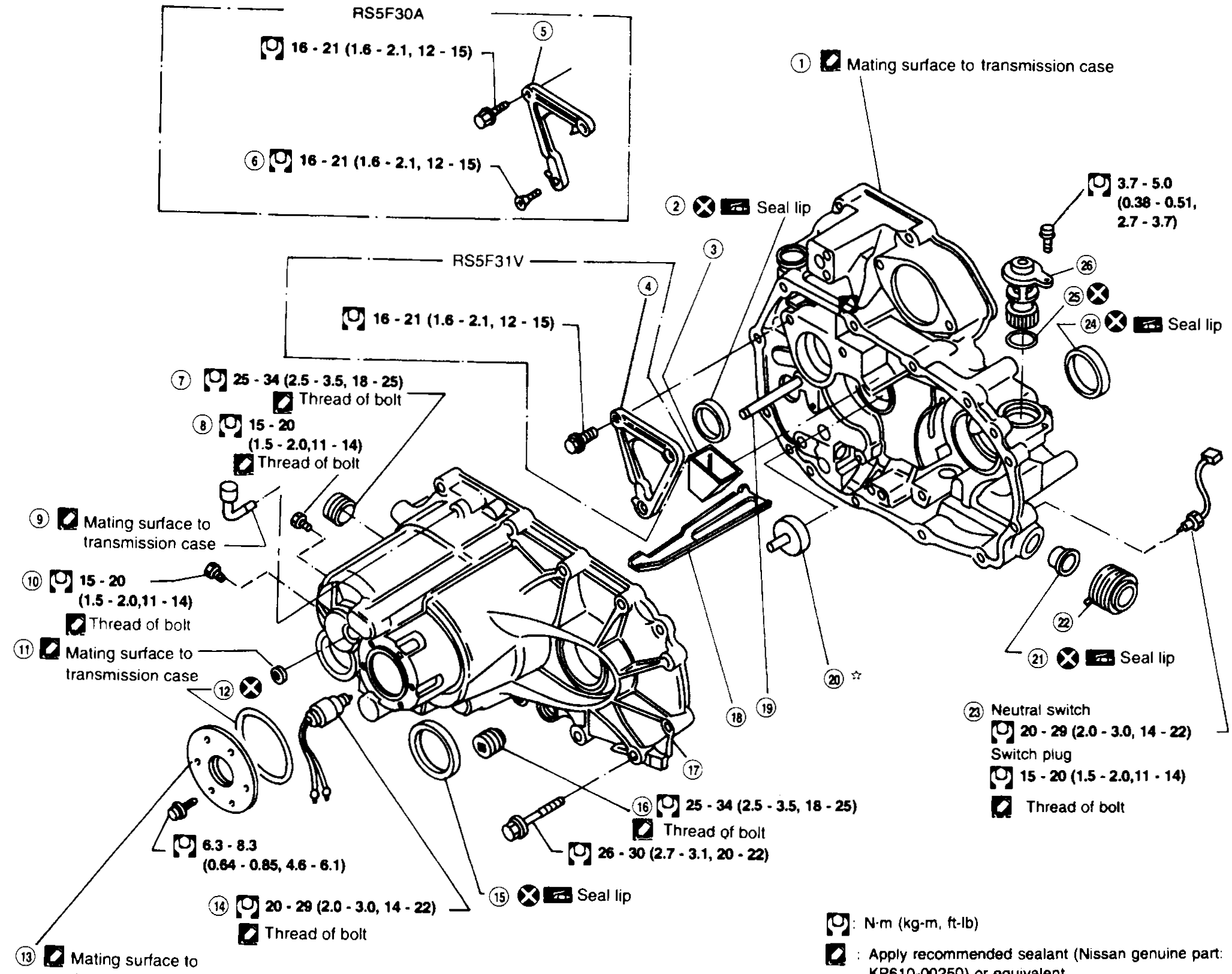
MAJOR OVERHAUL — Case Components (RS5F30A & RS5F31V)
MT-35Full-page exploded view of the RS5F30A and RS5F31V transaxle case components. Numbered callouts 1-26 identify clutch housing, input shaft oil seal, oil pocket, two bearing retainers, torx screw, filler plug, switch plugs, air breather, switch plug, welch plug, O-ring, case cover, reverse lamp switch, differential oil seal, drain plug, transmission case, oil gutter, reverse idler shaft, oil channel, striking rod oil seal, boot, neutral switch or switch plug, differential oil seal, O-ring, speedometer pinion assembly. Multiple torque callouts and sealant/seal-lip indicators around the perimeter, with legends: torque values in N·m (kg-m, ft-lb), apply recommended sealant (Nissan genuine part KP610-00250) or equivalent, and 'Pay attention to its direction' arrow.
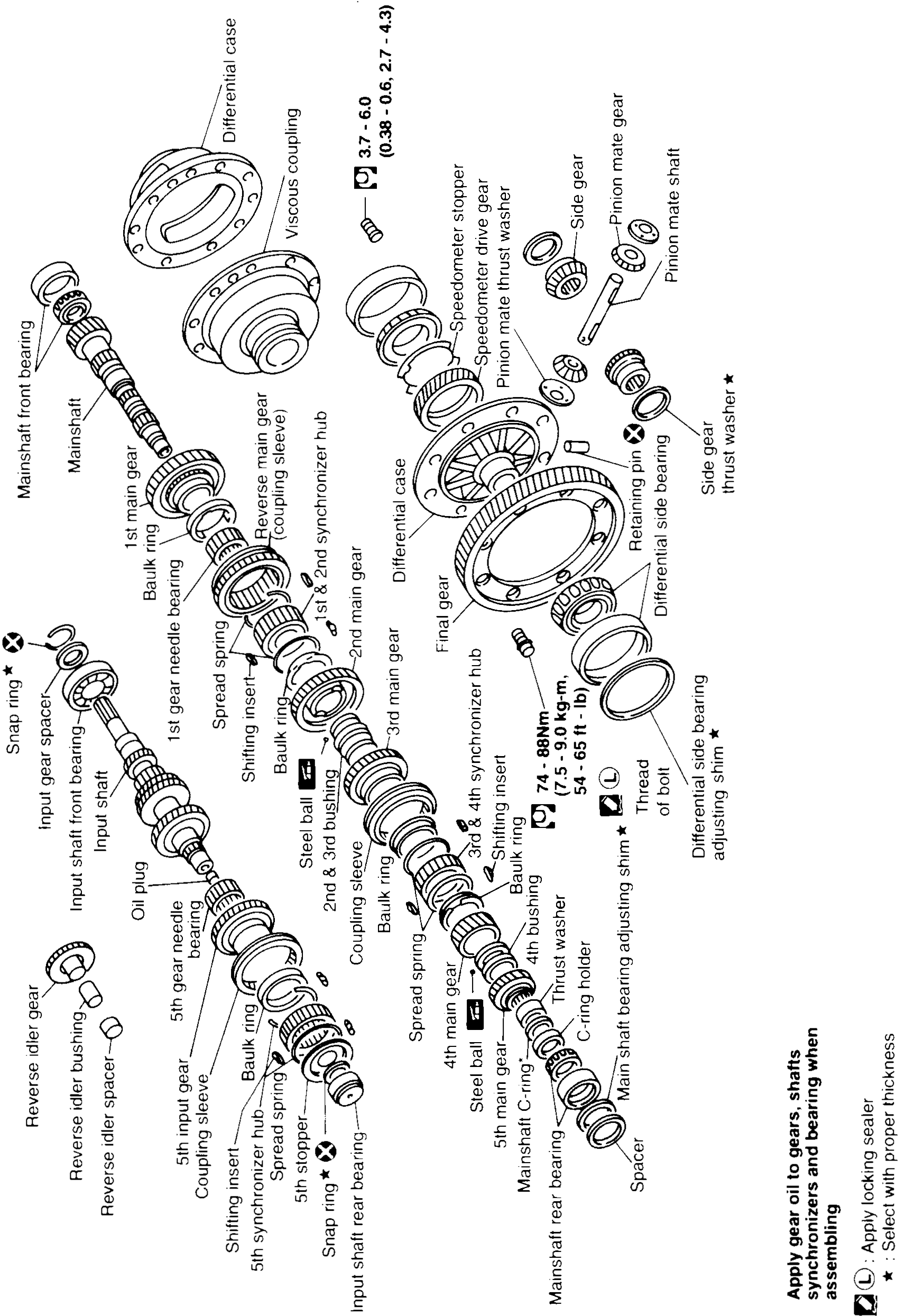
MAJOR OVERHAUL — Gear Components (RS5F30A & RS5F31V)
MT-36Full-page exploded view of the RS5F30A & RS5F31V transaxle gear components. Centre-top features the differential case with viscous coupling, final gear, speedometer drive gear, speedometer stopper, pinion mate thrust washer, pinion mate gear, pinion mate shaft, retaining pin, side gear, side gear thrust washer, differential side bearing, differential side bearing adjusting shim. Centre stack: mainshaft front bearing, mainshaft, 1st main gear, 1st gear needle bearing, baulk ring, reverse main gear (coupling sleeve), 1st & 2nd synchronizer hub, shifting insert, spread spring, 2nd main gear, 3rd main gear, 3rd & 4th synchronizer hub, baulk ring, 4th main gear, 5th main gear, mainshaft C-ring, C-ring holder, mainshaft rear bearing, mainshaft bearing adjusting shim. Left stack: input shaft front bearing, input shaft, oil plug, input shaft rear bearing, snap ring, input gear spacers, reverse idler bushing, reverse idler gear, reverse idler spacer, snap ring, 5th input gear, 5th synchronizer hub, 5th stopper, baulk ring, coupling sleeve, shifting insert, spread spring, steel ball, spacer, 2nd & 3rd bushing. Torque callout on differential-side bearing: 74 - 88 N·m (7.5 - 9.0 kg-m, 54 - 65 ft-lb). Reverse-lamp / case-cover-area callout 3.7 - 6.0 (0.38 - 0.6, 2.7 - 4.3) and 'Thread of bolt'. Legend bottom-right: 'Apply gear oil to gears, shafts, synchronizes and bearing when assembling', 'Apply locking sealer', '★ Select with proper thickness'.
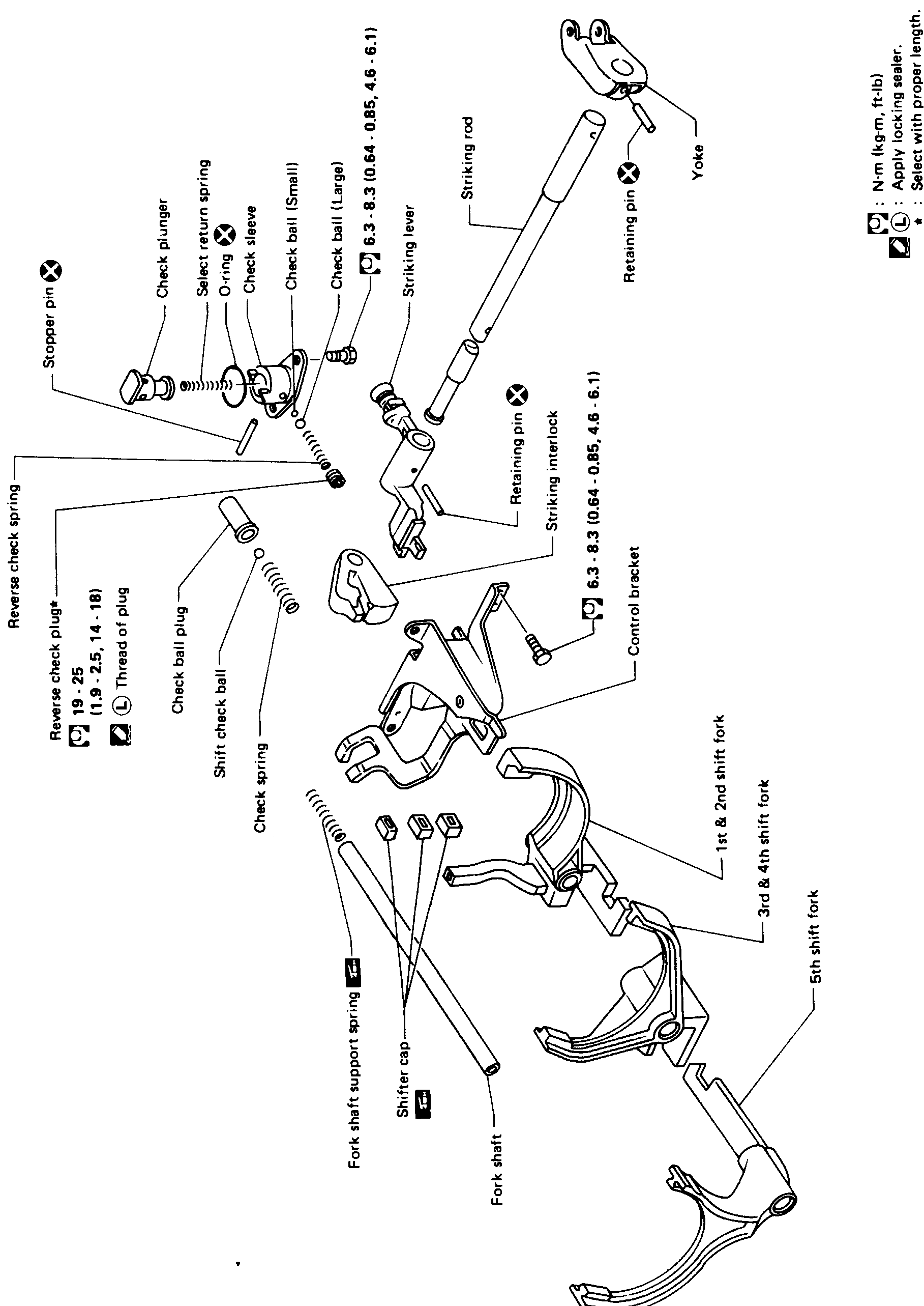
MAJOR OVERHAUL — Shift Control Components (RS5F30A & RS5F31V)
MT-37Full-page exploded view of the RS5F30A & RS5F31V shift control components. Top centre: yoke with retaining pin (X) joining the striking rod. Striking rod connects to striking lever with retaining pin. Left side: check assembly — check ball (Small), check ball (Large), O-ring (X), check sleeve, select return spring (★ select with proper length), check plunger, stopper pin (X), reverse check spring, reverse check plug (★), shift check ball, check ball plug, check spring. Centre: striking interlock attached to a control bracket. Bottom: 1st & 2nd shift fork, 3rd & 4th shift fork, 5th shift fork on a single fork shaft with shifter cap and fork shaft support spring. Torque callouts: 6.3 - 8.3 (0.64 - 0.85, 4.6 - 6.1) appears twice; 19 - 25 (1.9 - 2.5, 14 - 18). Legend top-right: N·m (kg-m, ft-lb); 'L' = Apply locking sealer; '★' = Select with proper length; X = Do not re-use.
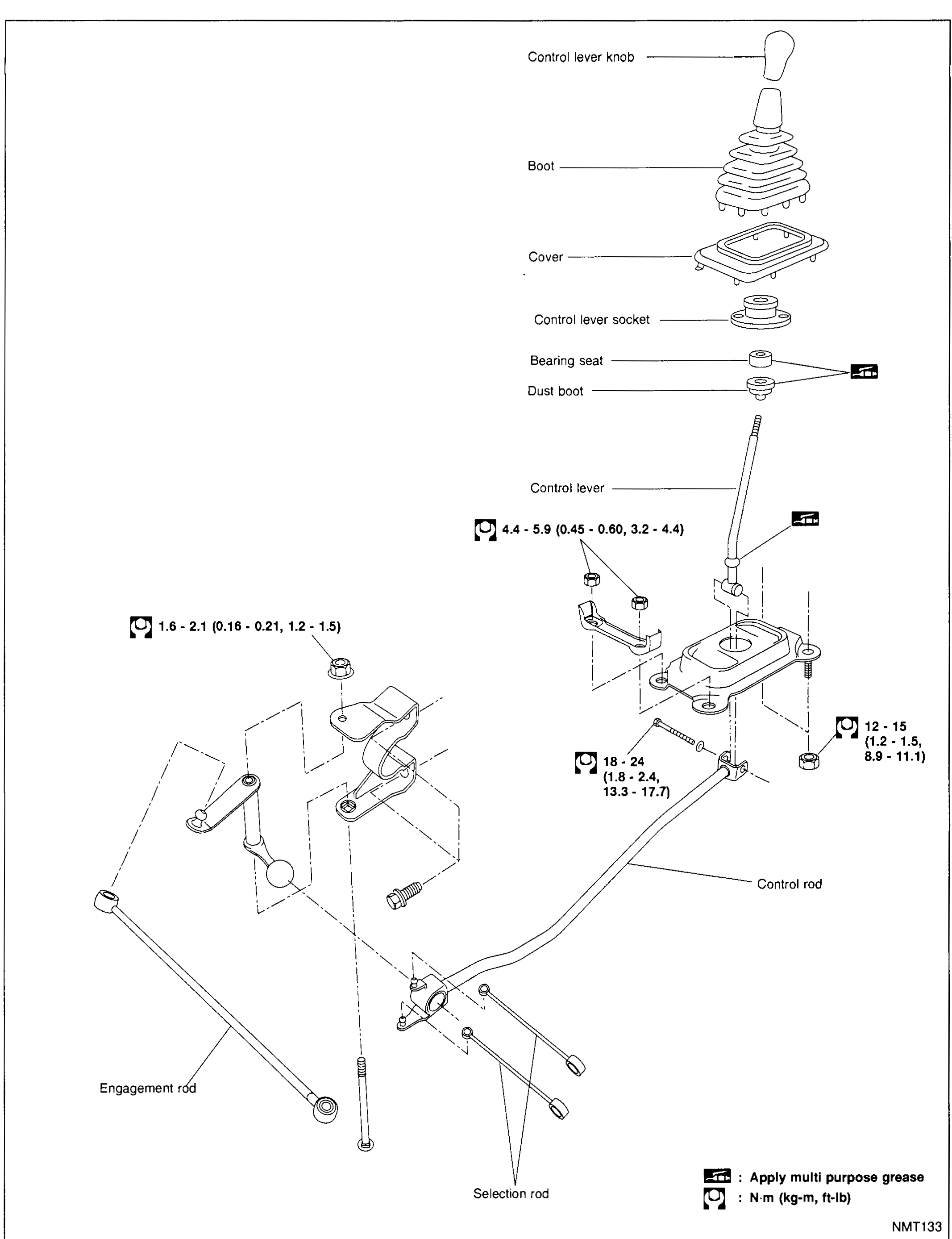
TRANSAXLE GEAR CONTROL (MA5L)
MT-5007Full-page exploded view of the MA5L gear-control linkage from the cabin floor down to the transaxle: control lever knob, boot, cover, control lever socket, bearing seat (apply multi-purpose grease), dust boot (apply multi-purpose grease), control lever, control rod, engagement rod and selection rod. Torque values are stamped at each fastener location.
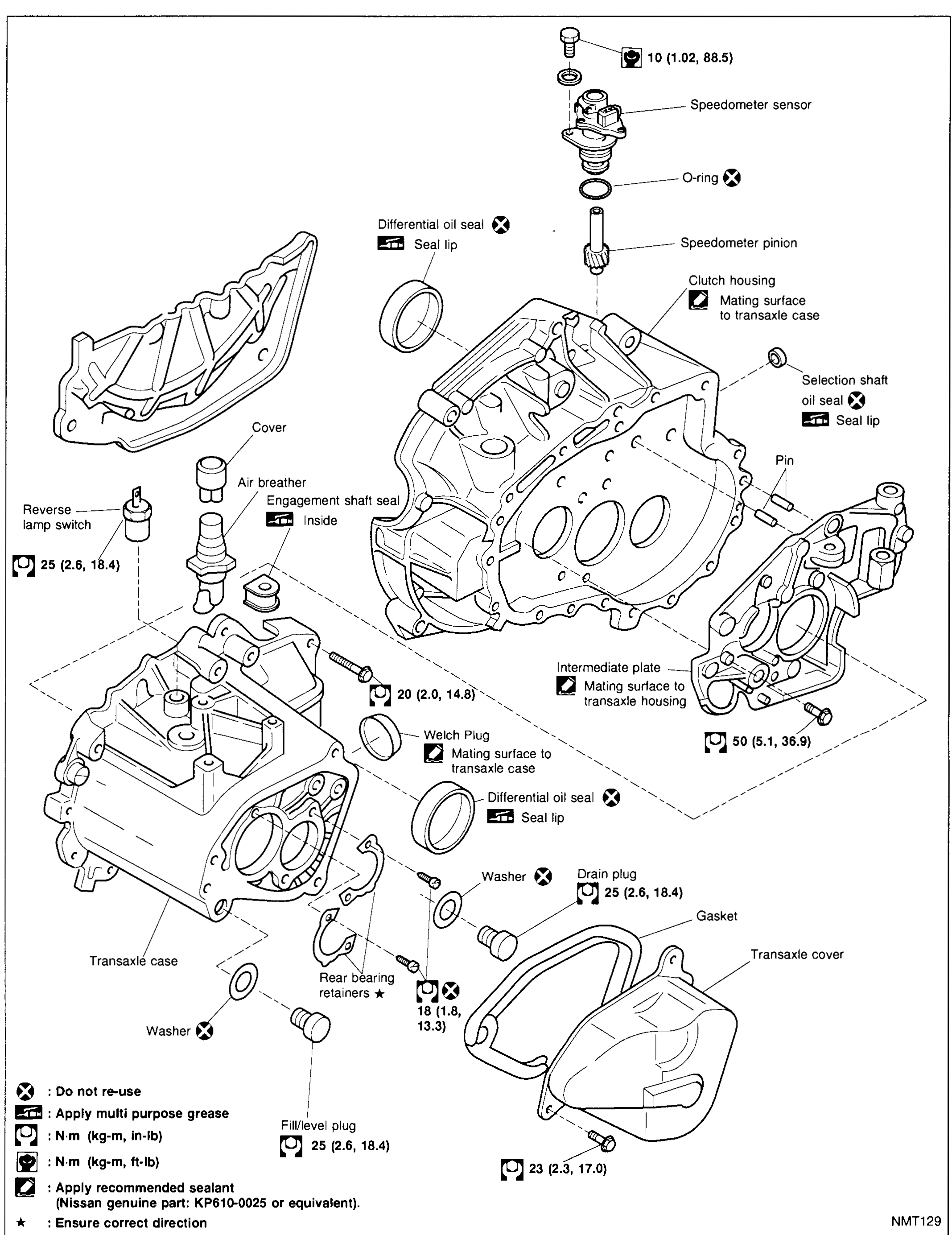
MAJOR OVERHAUL — Case components (MA5L)
MT-5008Full-page exploded view of the MA5L transaxle case components: clutch housing (with selection shaft oil seal, pin), intermediate plate, transaxle case (with welch plug, differential oil seal, rear bearing retainers), transaxle cover with gasket and drain/fill plugs, speedometer sensor + O-ring + pinion, reverse lamp switch, air breather, cover, and various washers. Annotations show torque values, grease/sealant points, and parts marked 'Do not re-use'.
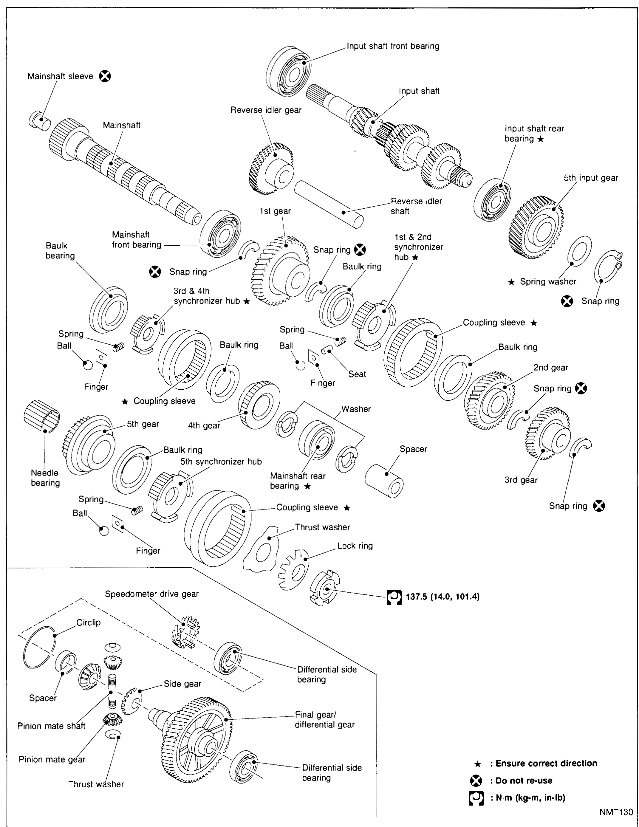
MAJOR OVERHAUL — Gear components (MA5L)
MT-5009Full-page exploded view of the MA5L gear-train: top-left mainshaft assembly (mainshaft sleeve, mainshaft, mainshaft front bearing, baulk bearing, 3rd & 4th synchronizer hub, 4th gear, 5th gear, needle bearing, mainshaft rear bearing, 5th synchronizer hub, coupling sleeve, thrust washer, lock ring); centre/top input shaft assembly (input shaft front bearing, reverse idler gear and shaft, input shaft, input shaft rear bearing, spring washer, 5th input gear, snap rings); right column showing 1st & 2nd synchronizer hub, baulk rings, coupling sleeves, 1st gear, 2nd gear, 3rd gear, snap rings, washer, spacer; bottom-left final drive / differential assembly (circlip, spacer, side gear, pinion mate shaft, pinion mate gear, thrust washer, differential side bearings, speedometer drive gear, final gear / differential gear).
MAJOR OVERHAUL — Shift Control Components (MA5L)
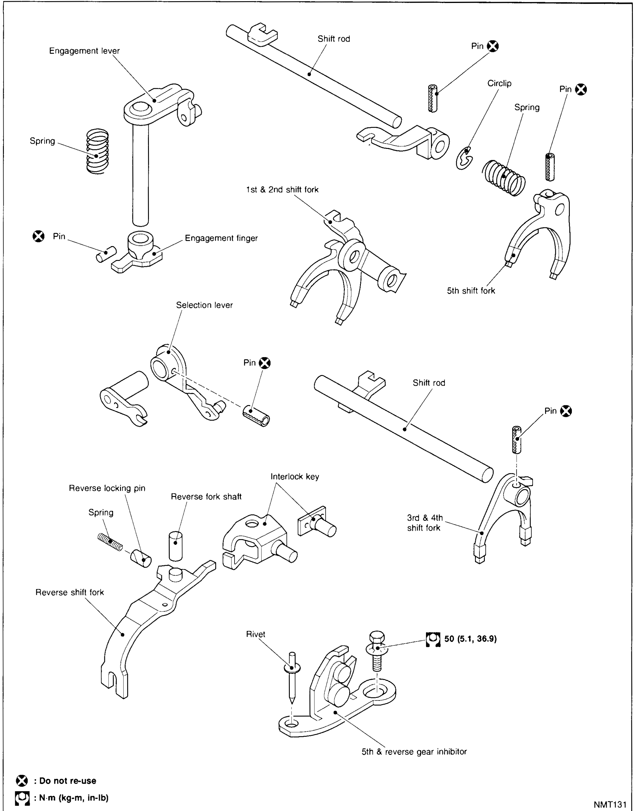
MT-5010Full-page exploded view of the MA5L shift control components: engagement lever (with spring, pin, engagement finger), upper shift rod with circlip and spring and pin holding 1st & 2nd and 5th shift forks; selection lever with pin; lower shift rod (with pin and 3rd & 4th shift fork); reverse-locking pin, reverse fork shaft, interlock key, reverse shift fork; rivet and 5th & reverse gear inhibitor (bolt torque 50 N·m).
Automatic Transmission
AT2 diagrams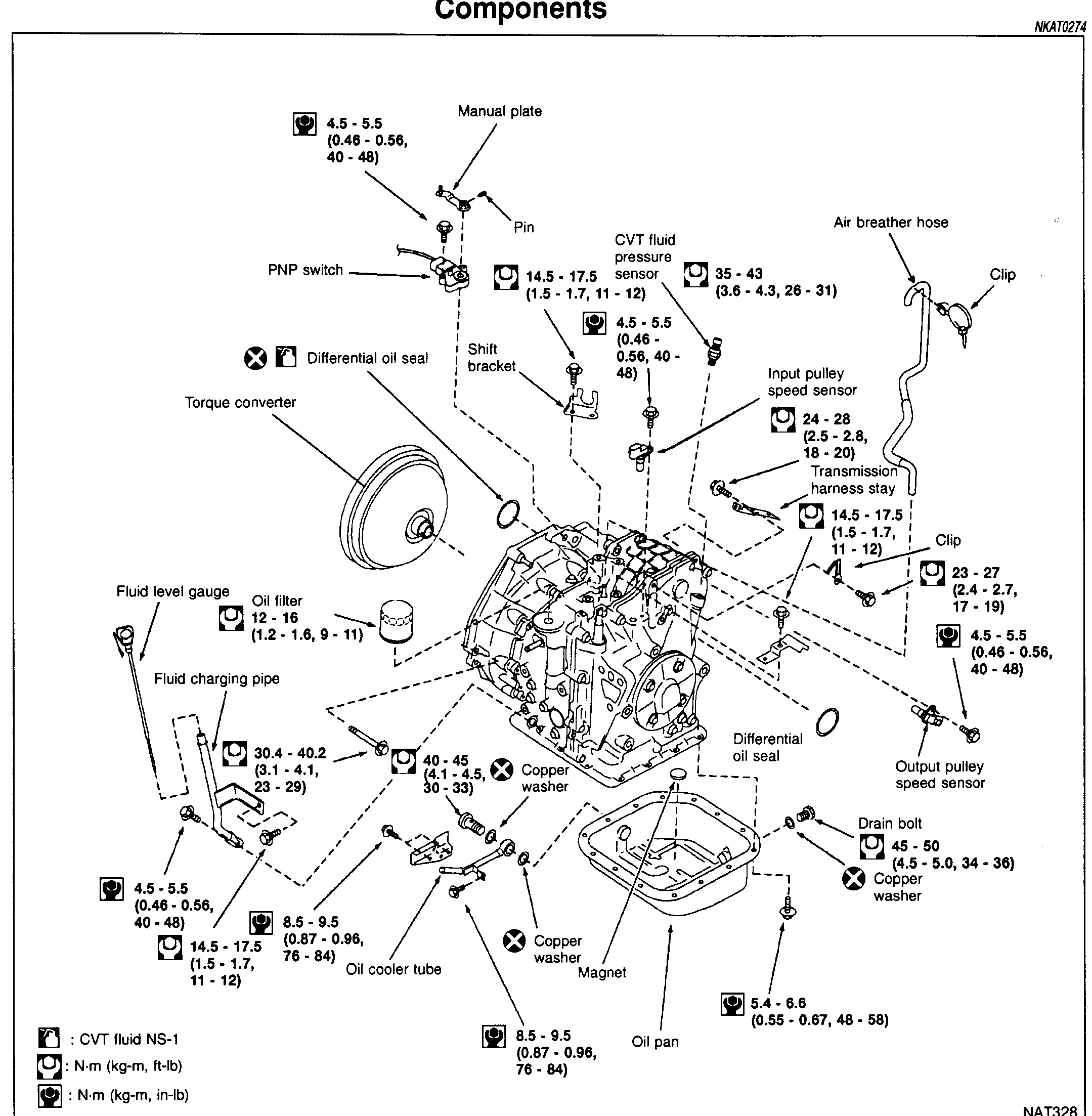
REMOVAL AND INSTALLATION — Components
AT-7126Exploded view of the CVT transaxle external components: torque converter, fluid level gauge, fluid charging pipe, oil filter, manual plate, PNP switch, differential oil seals (LH and RH), shift bracket, CVT fluid pressure sensor, input/output pulley speed sensors, transmission harness stay, air breather hose with clip, oil pan with magnet, copper washers, drain bolt, oil cooler tube. Each fixing point shows torque values; '×' markers indicate 'apply CVT fluid NS-1' before assembly.
REMOVAL AND INSTALLATION - Components
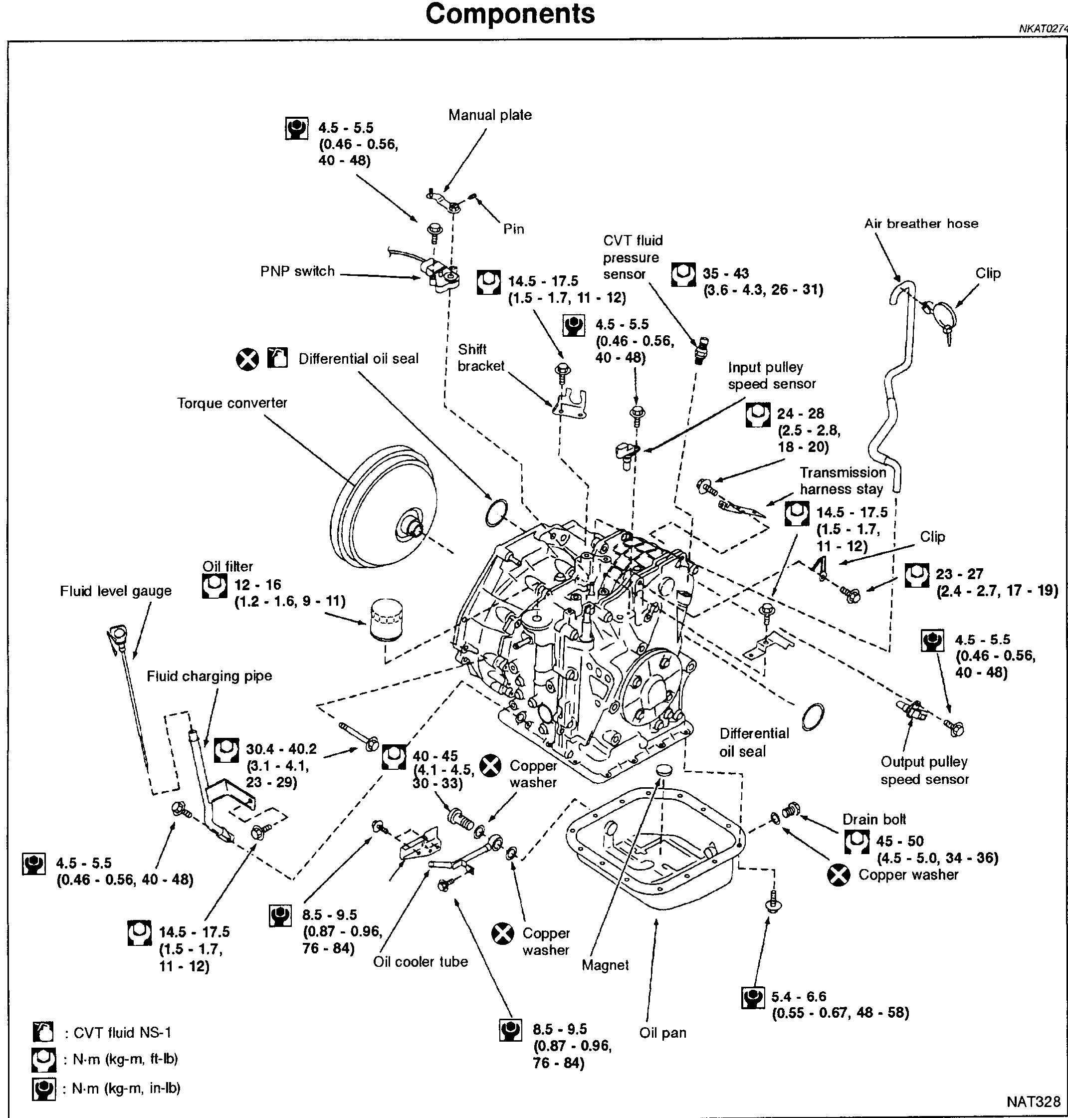
AT-7129Exploded view of CVT transaxle components with torque values: Manual plate, PNP switch, Pin, Shift bracket, CVT fluid pressure sensor, Input pulley speed sensor, Transmission harness stay, Air breather hose, Clip, Output pulley speed sensor, Drain bolt, Copper washer, Differential oil seal, Torque converter, Fluid level gauge, Oil filter, Fluid charging pipe, Oil cooler tube, Oil pan, Magnet
Front Axle & Front Suspension
FA3 diagrams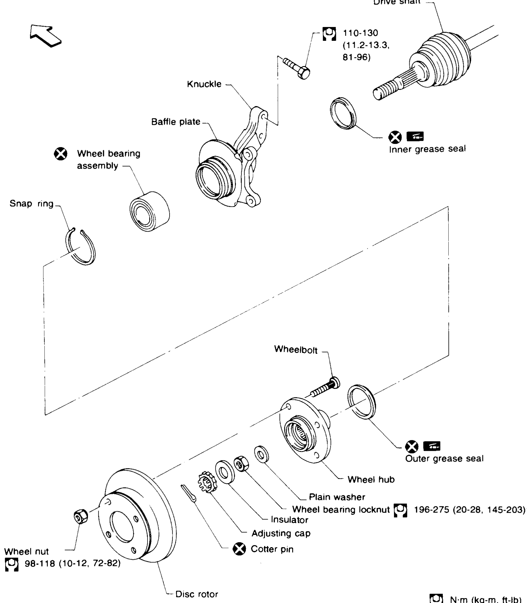
FRONT AXLE — Wheel Hub, Knuckle and Drive Shaft Components
FA-7Full-page exploded view of the K11 front wheel-hub and knuckle assembly. Top half: Knuckle in centre with Baffle plate attached, Wheel-bearing assembly with Snap ring on its left, Drive shaft with Inner grease seal on the right. The knuckle-to-strut bolt has a 110–130 (11.2–13.3, 81–96) N·m torque callout. Bottom half: Disc rotor at left, Wheel hub with Wheelbolt and Outer grease seal, then stacked sequence going inboard: Plain washer, Insulator, Adjusting cap, Cotter pin, Wheel bearing locknut with 196–275 (20–28, 145–203) N·m torque. Wheel nut on rotor has 98–118 (10–12, 72–82) N·m torque. An 'X' (do-not-reuse) symbol marks: Wheel bearing assembly, Inner grease seal, Outer grease seal, Cotter pin. Legend at bottom-right: wrench icon = N·m (kg-m, ft-lb). A small directional arrow at top-left indicates orientation.
FRONT AXLE — Drive Shaft (Installation Cont'd / Components)
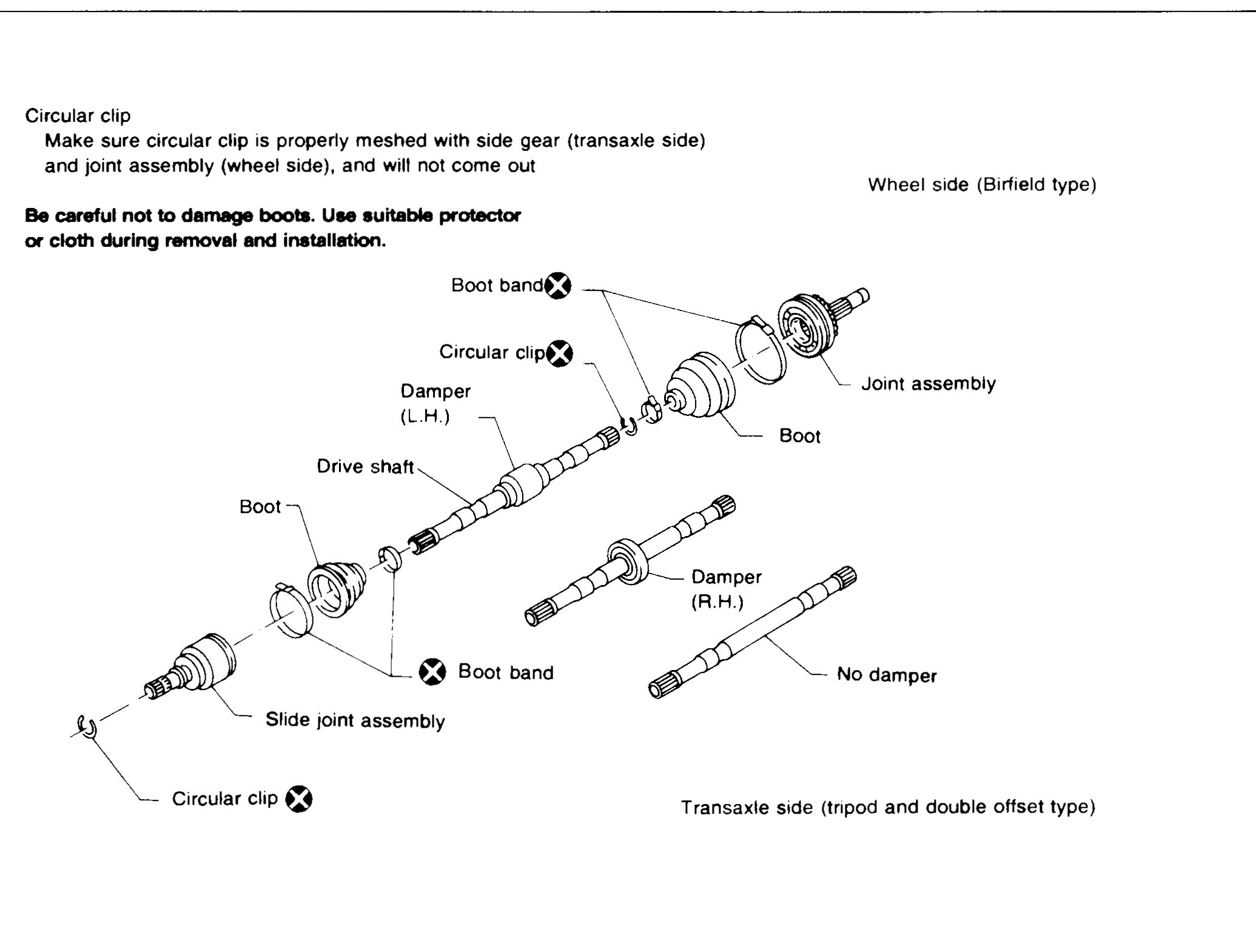
FA-14Exploded view of the K11 front drive-shaft components. From wheel side (right, labelled 'Wheel side (Birfield type)') going inboard: Joint assembly (outer CV), Boot, Circular clip (X marker), Boot band (X marker), Drive shaft, Damper (L.H. version on the shown shaft and a separate shorter shaft with Damper (R.H.); a third shaft labelled 'No damper'), Boot, Slide joint assembly (inner CV — labelled 'Transaxle side (tripod and double offset type)'), Boot band (X marker), Circular clip (X marker). Notes at top-left: 'Make sure circular clip is properly meshed with side gear (transaxle side) and joint assembly (wheel side), and will not come out' and 'Be careful not to damage boots. Use suitable protector or cloth during removal and installation.'
FRONT SUSPENSION — Components
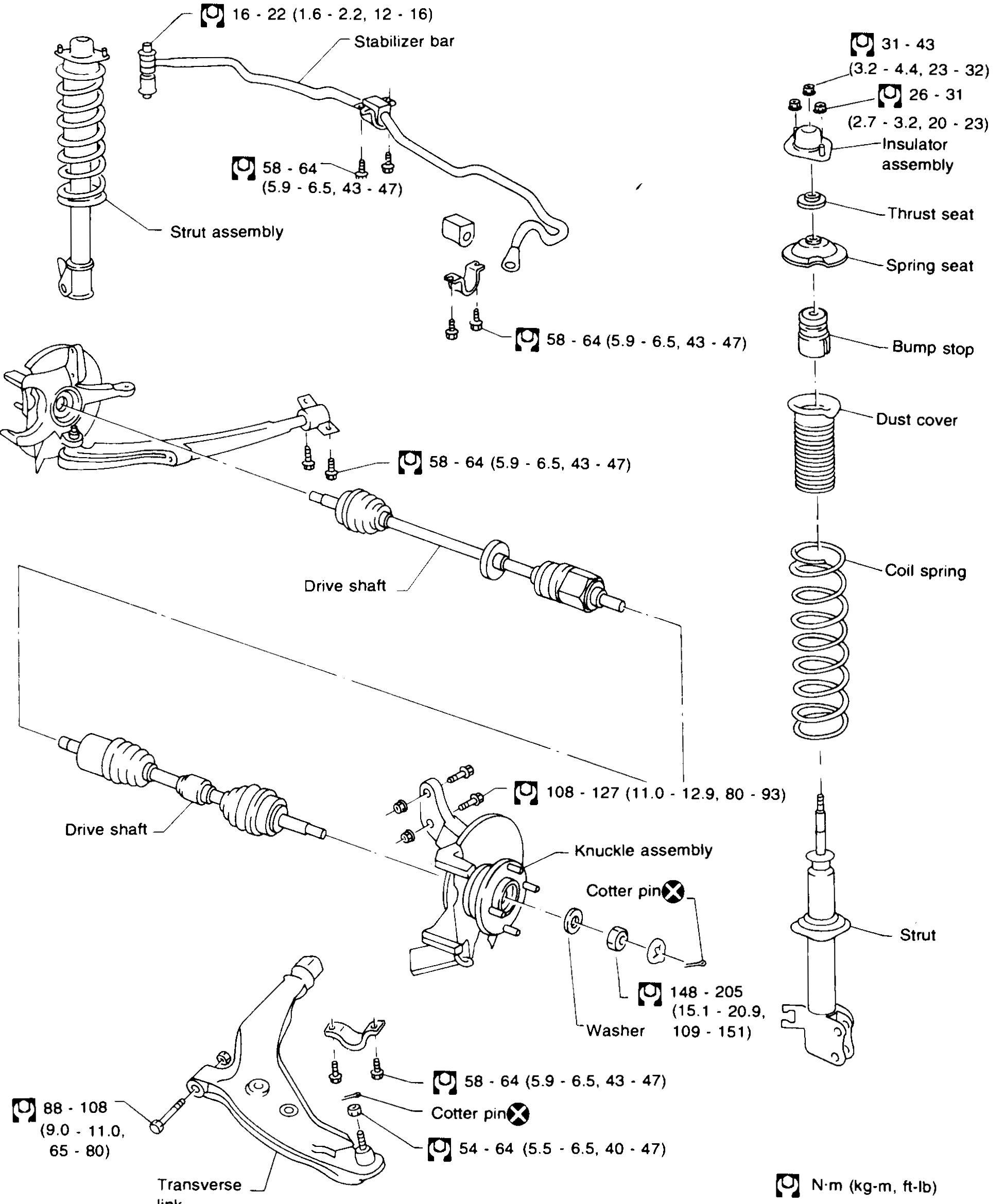
FA-18Full-page exploded view of the K11 front suspension. Top-left: Strut assembly with coil spring attached to a Stabilizer bar (with mounting clamps and connecting links). Centre: Drive shaft running into Knuckle assembly with Cotter pin (X marker), Washer; Transverse link (lower control arm) at bottom. Right column: vertical stack of strut components — Insulator assembly, Thrust seat, Spring seat, Bump stop, Dust cover, Coil spring, Strut. Torque callouts (wrench icon) annotate each fastener. Legend bottom-right: 'N·m (kg-m, ft-lb)'. Cotter pins are marked with 'X' (do-not-reuse).
Rear Axle & Rear Suspension
RA2 diagrams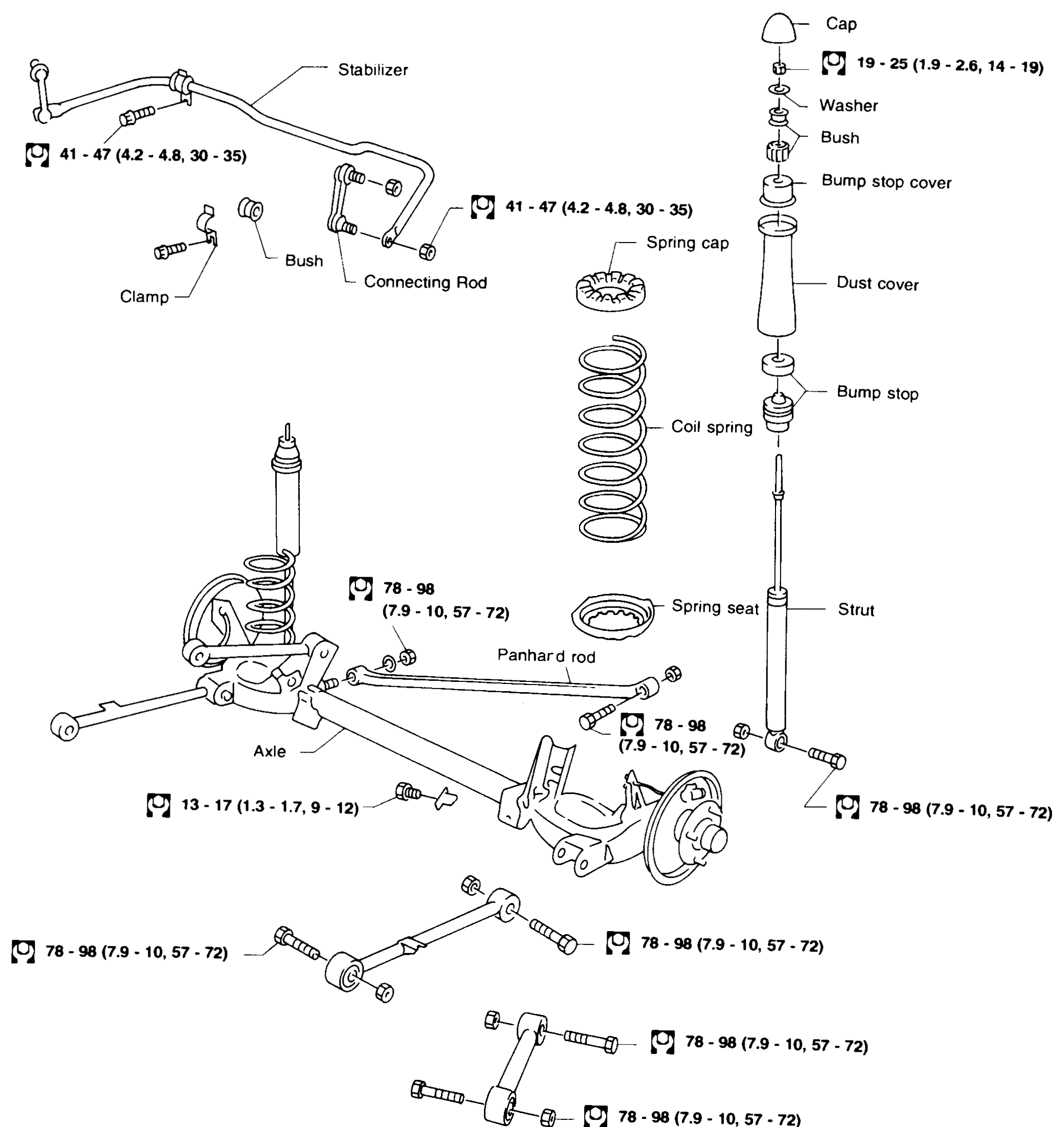
REAR AXLE AND REAR SUSPENSION
RA-3Full exploded view of the K11 rear axle and rear suspension assembly. Top-left shows the stabilizer bar with clamp, bush, and connecting rod. Top-right shows the strut tower components stacked vertically: cap, washer, bush, bump stop cover, dust cover, spring cap, coil spring, bump stop, spring seat, strut. Centre shows the axle beam, Panhard rod, and lower control-arm links. Torque values are called out next to each fastener with the legend N·m (kg-m, ft-lb).
REAR AXLE — Wheel Hub
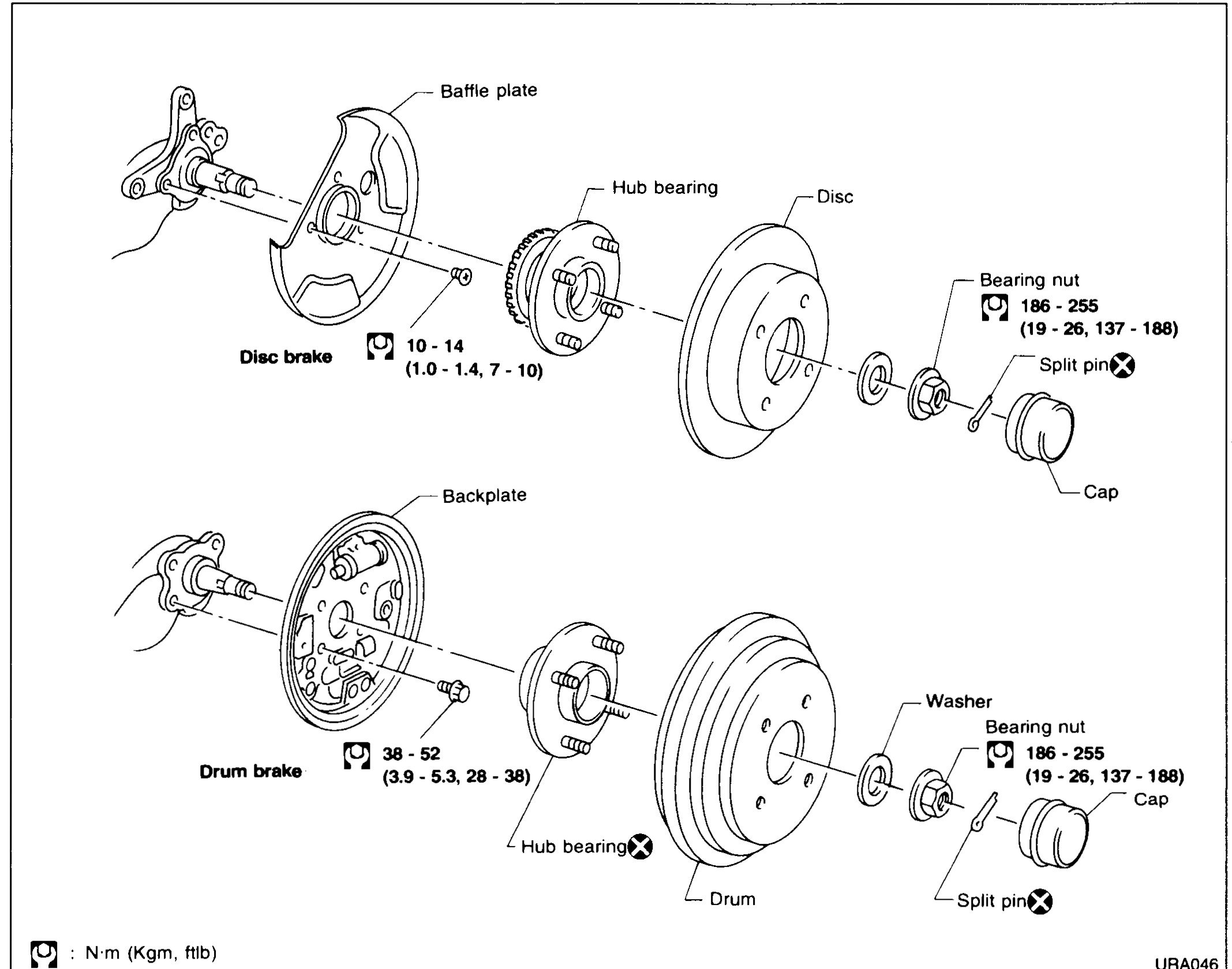
RA-6Exploded views of the rear wheel-hub assembly in two variants stacked vertically. Top variant 'Disc brake': from left to right — disc-brake backing plate / stub axle, Baffle plate, Hub bearing, Disc, Bearing nut, Cap, Split pin. Bottom variant 'Drum brake': from left to right — drum-brake backplate / stub axle, Hub bearing, Drum, Washer, Bearing nut, Cap, Split pin. Torque callouts: 10–14 (1.0–1.4, 7–10) for baffle-plate bolts on the disc-brake variant; 38–52 (3.9–5.3, 28–38) for backplate bolts on the drum-brake variant; 186–255 (19–26, 137–188) for the bearing nut on both. Legend at bottom-left: N·m (kg-m, ft-lb). Note: 'Hub bearing' on the drum variant has an 'X' (do-not-reuse) marker.
Brake System
BR6 diagrams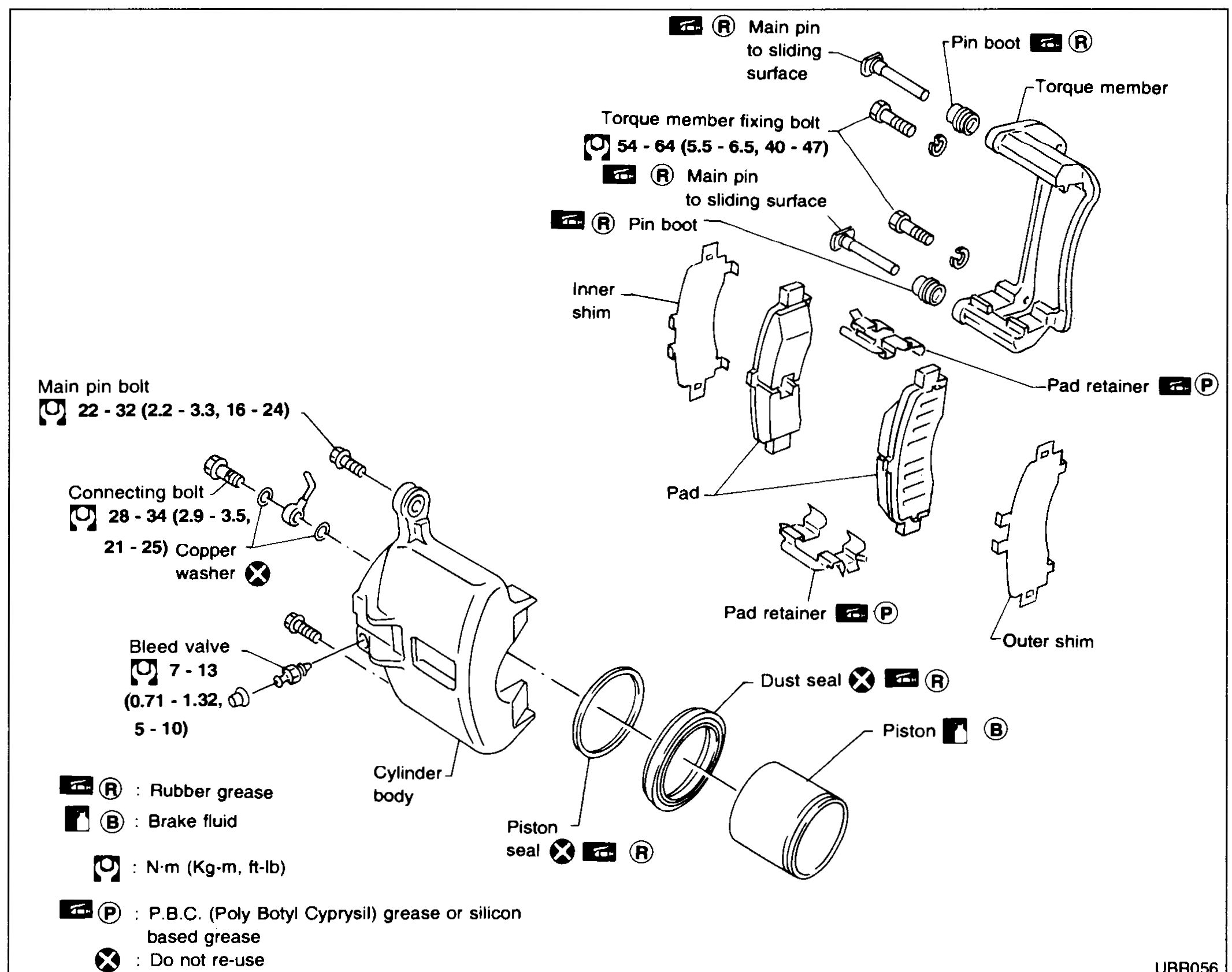
FRONT DISC BRAKE — Exploded view / Removal
BR-18Front disc-brake caliper exploded view: torque member with two main pins (with pin boots) and torque-member fixing bolts; cylinder body with main pin bolt, connecting bolt + copper washer, bleed valve, piston seal, dust seal and piston; pad pack (inner shim, pad, outer shim) with pad retainers. Legend explains rubber-grease, brake-fluid, do-not-re-use, and PBC grease icons. Torques: torque-member fixing bolt 54-64 N·m (5.5-6.5 kg·m, 40-47 ft·lb); main-pin bolt 22-32 N·m (2.2-3.3 kg·m, 16-24 ft·lb); connecting bolt 28-34 N·m (2.9-3.5 kg·m, 21-25 ft·lb); bleed valve 7-13 N·m (0.71-1.32 kg·m, 5-10 ft·lb).
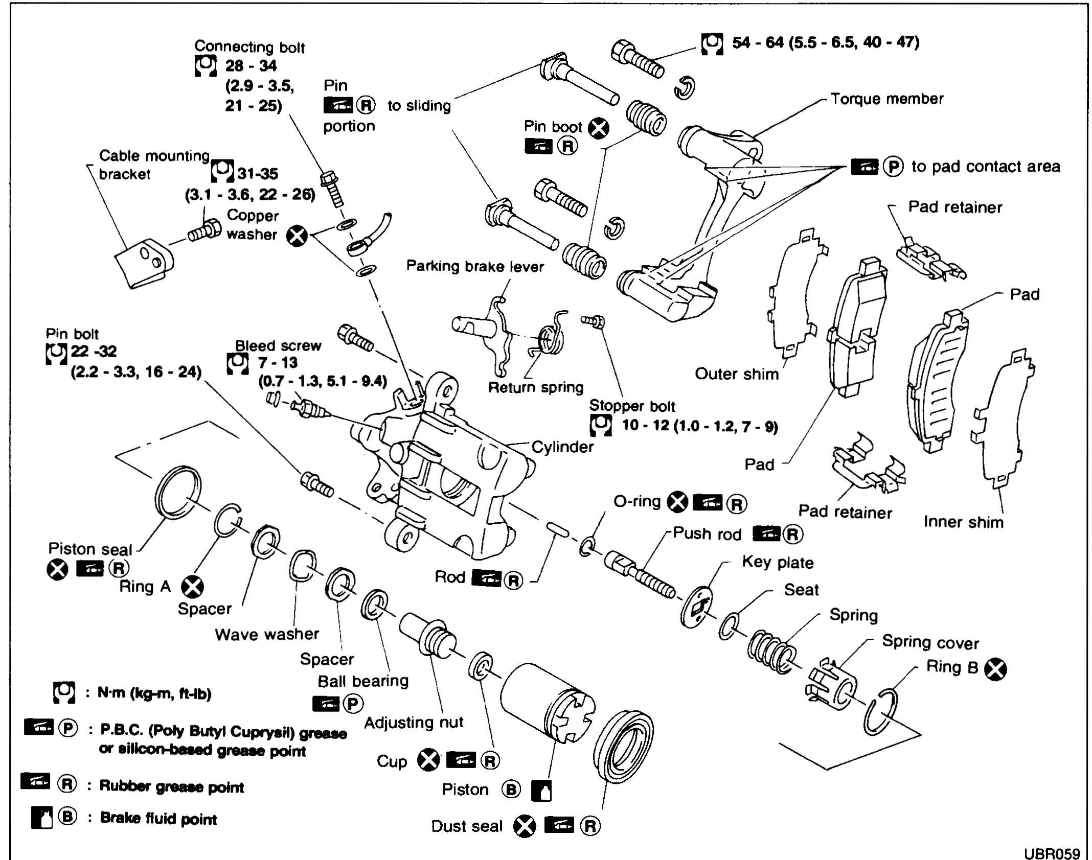
REAR DISC BRAKE — Exploded view / Removal
BR-22Rear disc-brake caliper exploded view: torque member with main pin (with pin boot) and torque-member fixing bolts; cylinder body with pin bolt, connecting bolt + copper washer, bleed screw, stopper bolt, return spring, parking brake lever, piston seal + ring A, dust seal + ring B, push rod with O-ring, key plate, seat, spring, spring cover, adjusting nut (with cup), wave washer, spacer, ball bearing, piston, rod; pad pack (inner shim, pad, outer shim) with pad retainers. Legend explains rubber-grease, brake-fluid, PBC-grease, and do-not-re-use icons. Torques: torque-member fixing bolt 54-64 N·m (5.5-6.5 kg·m, 40-47 ft·lb); connecting bolt 28-34 N·m (2.9-3.5 kg·m, 21-25 ft·lb); cable-mounting copper-washer bolt 31-35 N·m (3.1-3.6 kg·m, 22-26 ft·lb); pin bolt 22-32 N·m (2.2-3.3 kg·m, 16-24 ft·lb); bleed screw 7-13 N·m (0.7-1.3 kg·m, 5.1-9.4 ft·lb); stopper bolt 10-12 N·m (1.0-1.2 kg·m, 7-9 ft·lb).
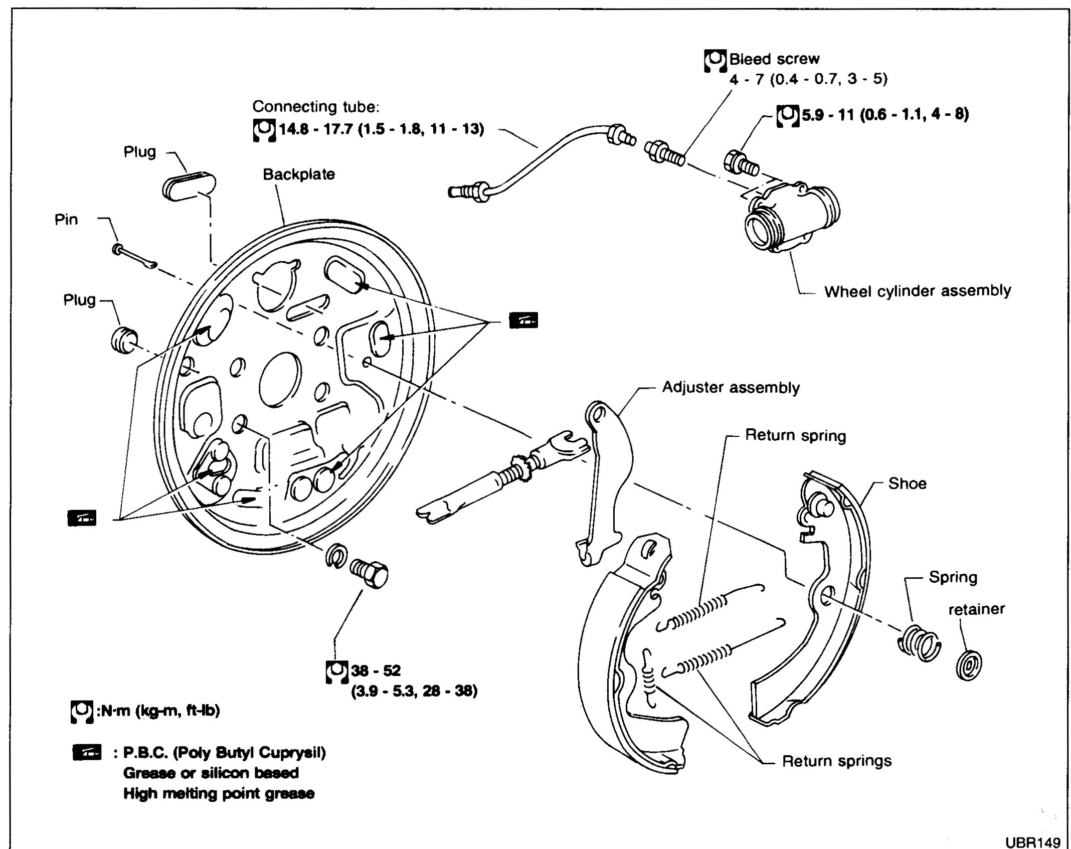
REAR DRUM BRAKE — Exploded view / Removal
BR-27Rear drum-brake exploded view: backplate with two plugs and a wheel-cylinder-side bleed screw; connecting tube; wheel cylinder assembly bolted to backplate; primary and secondary shoes with return springs (upper and lower), spring retainers, and adjuster assembly. Legend shows P.B.C. (Poly Butyl Cuprysil) grease or silicon-based high-melting-point grease icon. Torques: backplate-to-axle bolts 38-52 N·m (3.9-5.3 kg·m, 28-38 ft·lb); wheel-cylinder mounting nut 5.9-11 N·m (0.6-1.1 kg·m, 4-8 ft·lb); connecting tube 14.8-17.7 N·m (1.5-1.8 kg·m, 11-13 ft·lb); bleed screw 4-7 N·m (0.4-0.7 kg·m, 3-5 ft·lb).
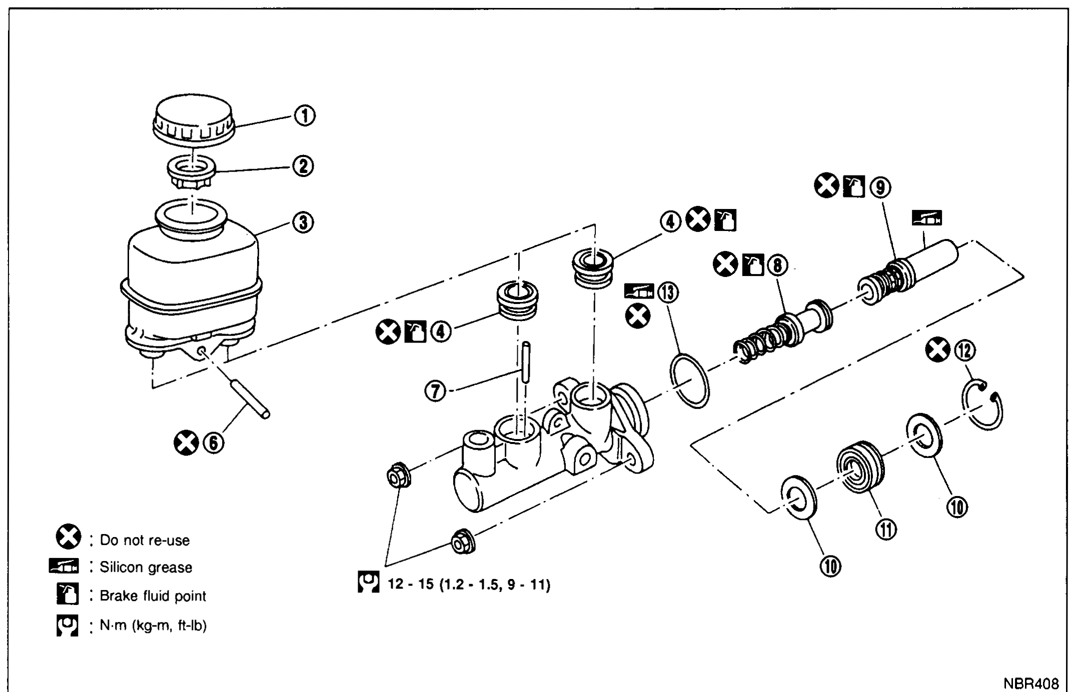
MASTER CYLINDER (NABCO)
BR-7007Exploded view of the NABCO master cylinder. Shows reservoir cap (1), filter (2), reservoir tank (3), seal (4), cylinder body, elastic pin (6), piston stopper pin (7), secondary piston assembly (8), primary piston assembly (9), seal (10), piston guide assembly (11), circlip (12), O-ring seal (13), stopper cap (14), O-ring (15). Torque value 12-15 N·m (1.2-1.5 kg-m, 9-11 ft-lb) for the reservoir tank mounting fastener. Legend symbols indicate: 'Do not re-use', 'Silicon grease', 'Brake fluid point', and torque marking.
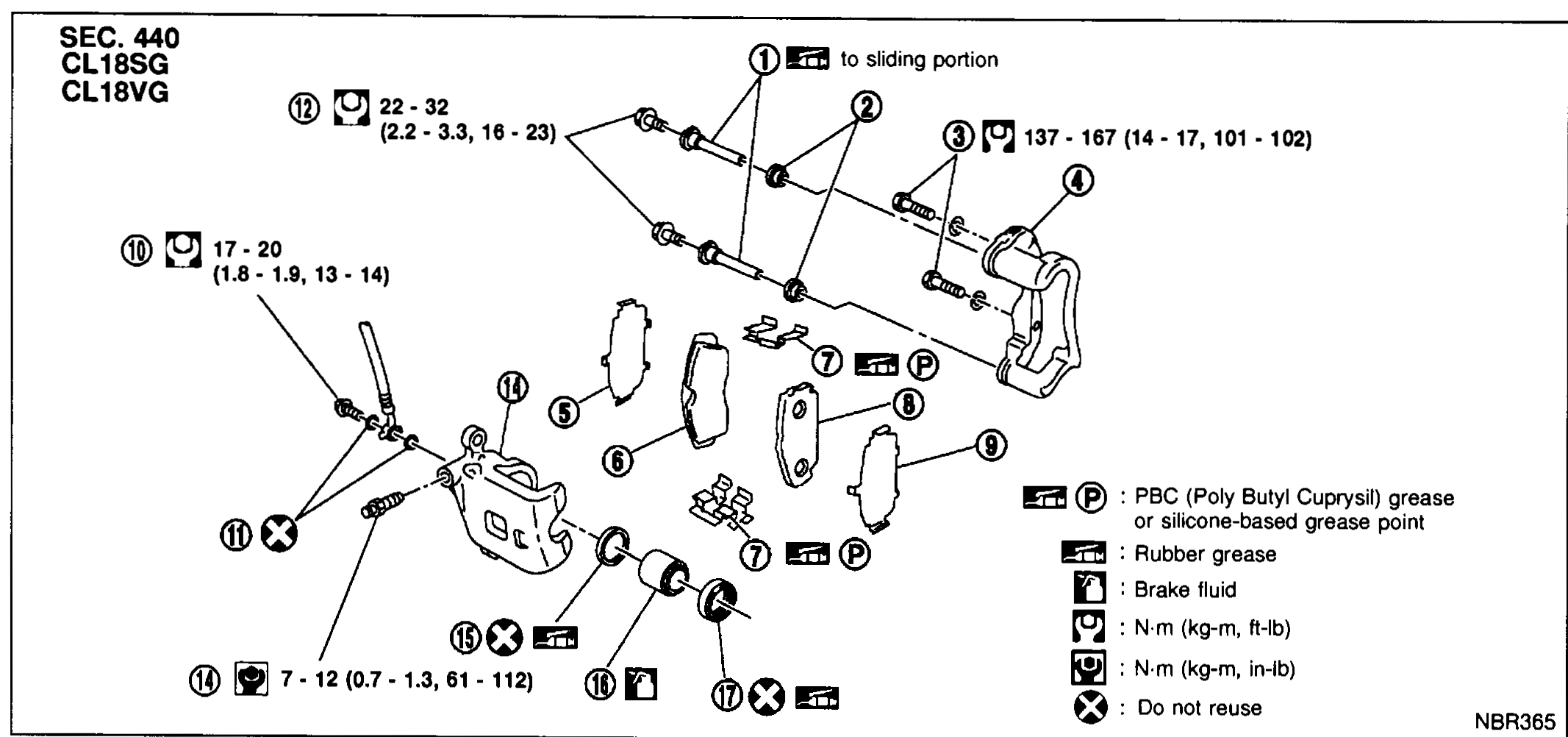
FRONT DISC BRAKE
BR-7012Exploded view of CL18SG/CL18VG front disc brake caliper assembly (SEC. 440) showing main pin, pin boot, torque member fixing bolt (137-167 N·m), torque member, inner shim, inner pad, pad retainer, outer pad, outer shim, connecting bolt (17-20 N·m), copper washer, main pin bolt (22-32 N·m), bleed valve (7-12 N·m), cylinder body, piston seal, piston, and piston boot. Includes legend for PBC grease, rubber grease, brake fluid, torque units, and do-not-reuse parts.
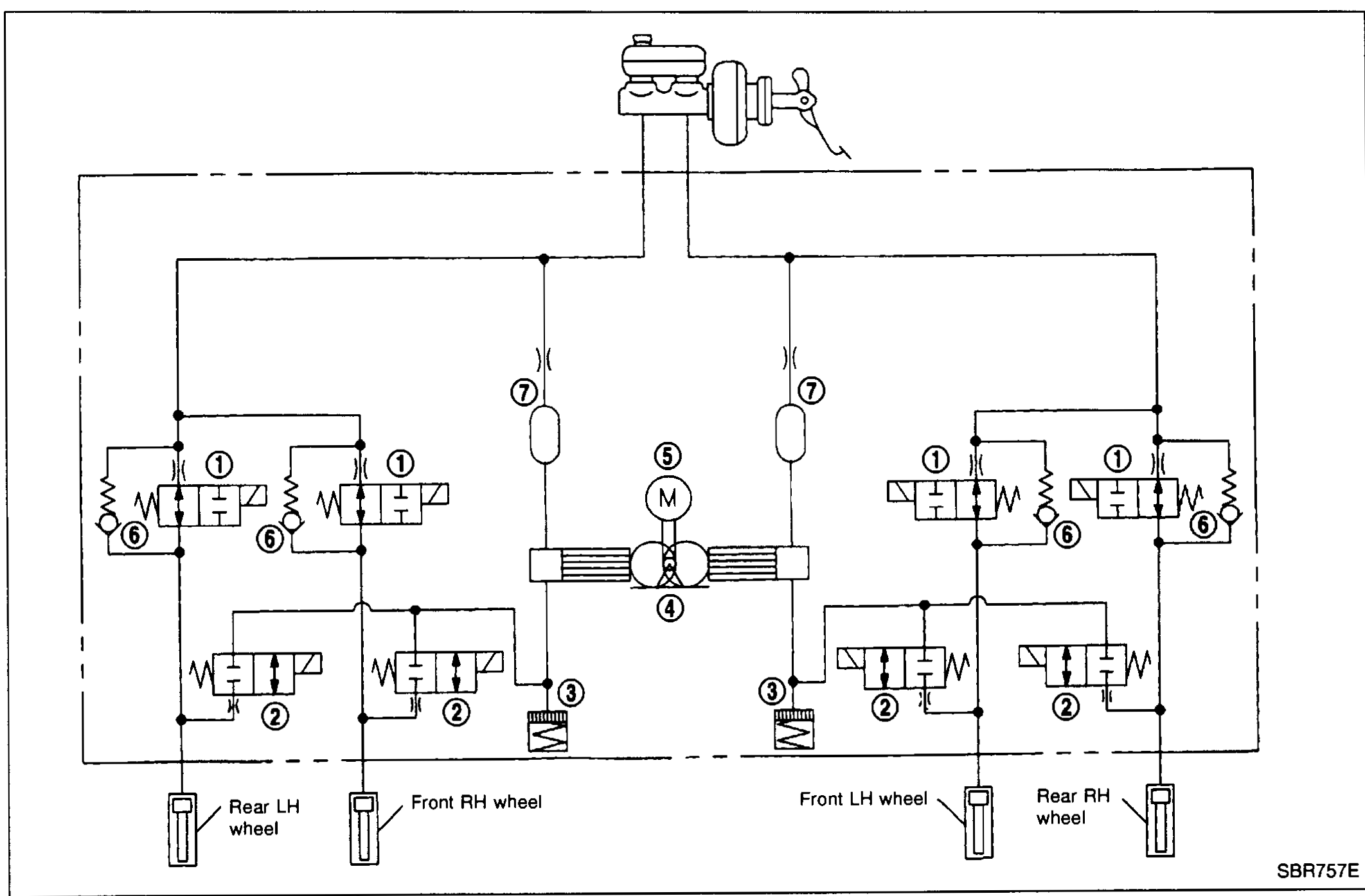
DESCRIPTION
BR-7014ABS hydraulic circuit schematic showing master cylinder at top, two front circuits (Front LH wheel, Front RH wheel) and two rear circuits (Rear LH wheel, Rear RH wheel), each with inlet solenoid valve (1), outlet solenoid valve (2), reservoir (3), bypass check valve (6), and damper (7). Central pump (4) and motor (5) shared between circuits.
Steering System
ST2 diagrams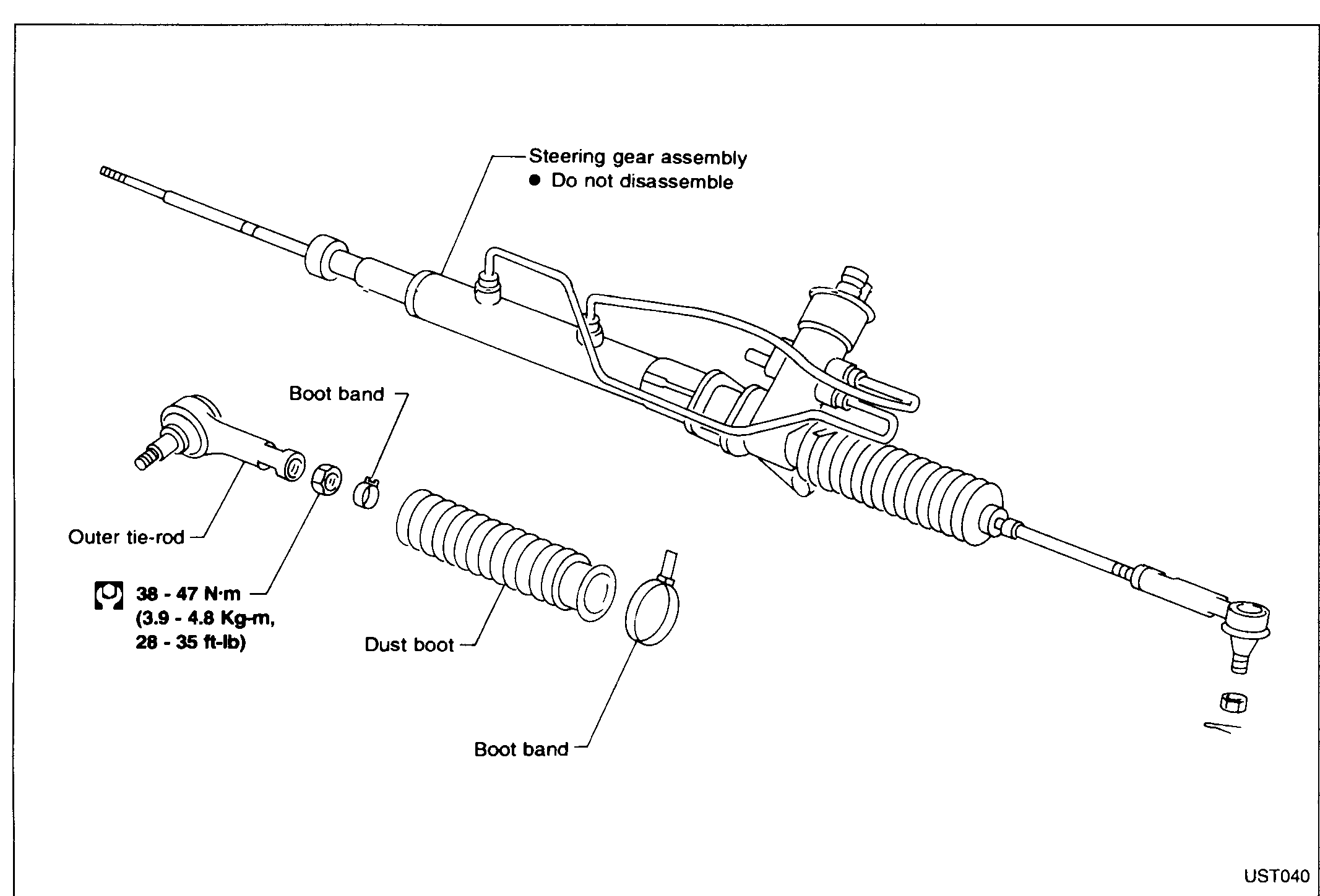
POWER STEERING GEAR AND LINKAGE
ST-25Exploded view of the power-steering gear assembly with both outer tie-rods, dust boots and boot bands separated from the main rack. Top callout reads 'Steering gear assembly — Do not disassemble'. Lower-left callouts identify the 'Outer tie-rod' and its tightening torque 38 - 47 N·m (3.9 - 4.8 Kg-m, 28 - 35 ft-lb), 'Boot band' (upper), 'Dust boot', and 'Boot band' (lower).
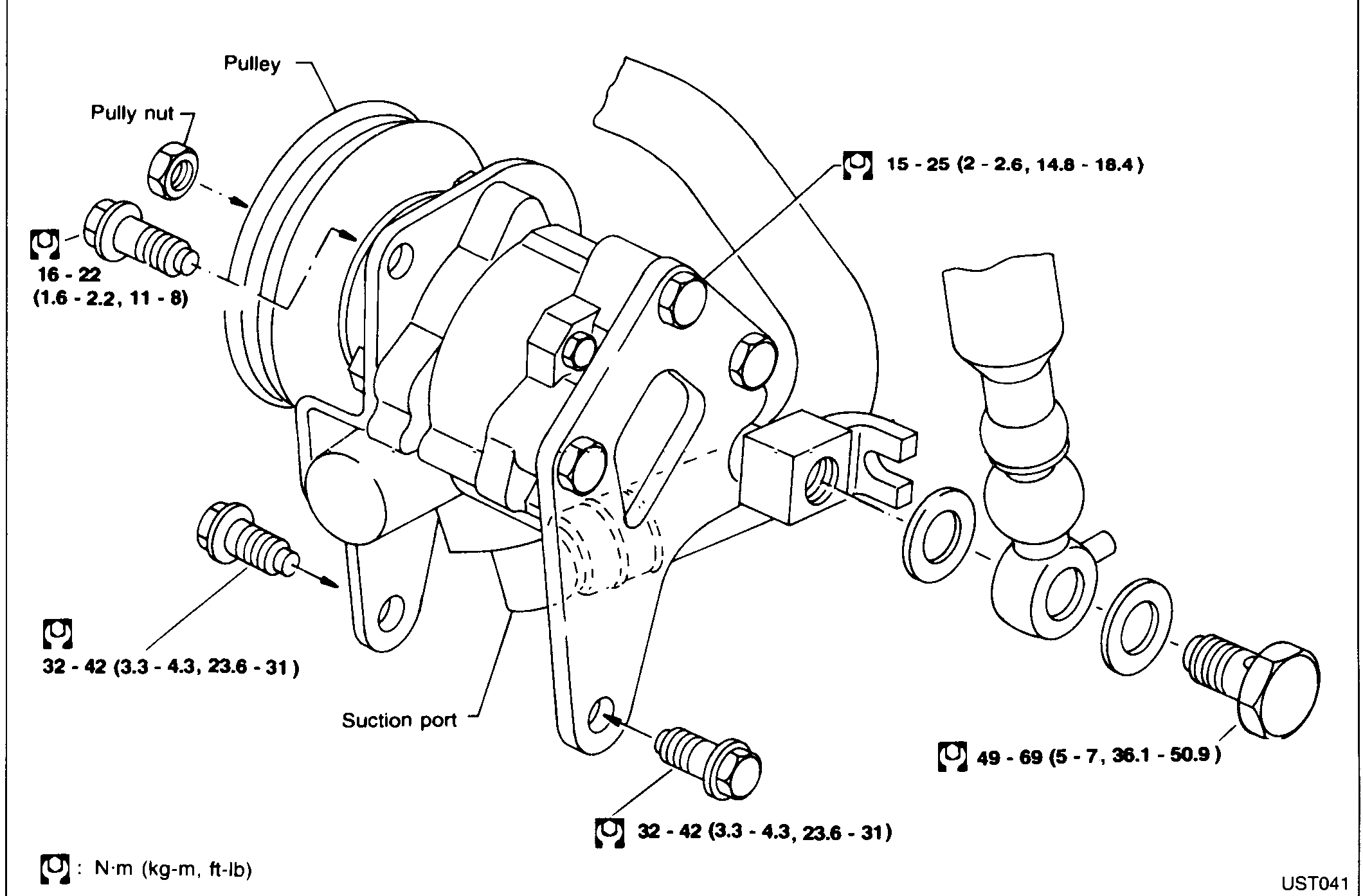
POWER STEERING OIL PUMP
ST-28Exploded view of the power-steering oil pump assembly. Callouts identify the 'Pulley' and 'Pully nut' (upper-left), pump mounting bolts and through-bolts on the bracket, the 'Suction port' on the rear of the pump, and the banjo union bolt with two washers at the high-pressure outlet (right). Tightening torques in N·m (kg-m, ft-lb) annotate each fastener: 16 - 22 (1.6 - 2.2, 11 - 8) for the pulley nut, 15 - 25 (2 - 2.6, 14.8 - 18.4) for the upper pump bolts, 32 - 42 (3.3 - 4.3, 23.6 - 31) for the bracket bolts, and 49 - 69 (5 - 7, 36.1 - 50.9) for the banjo bolt.
Body
BF7 diagrams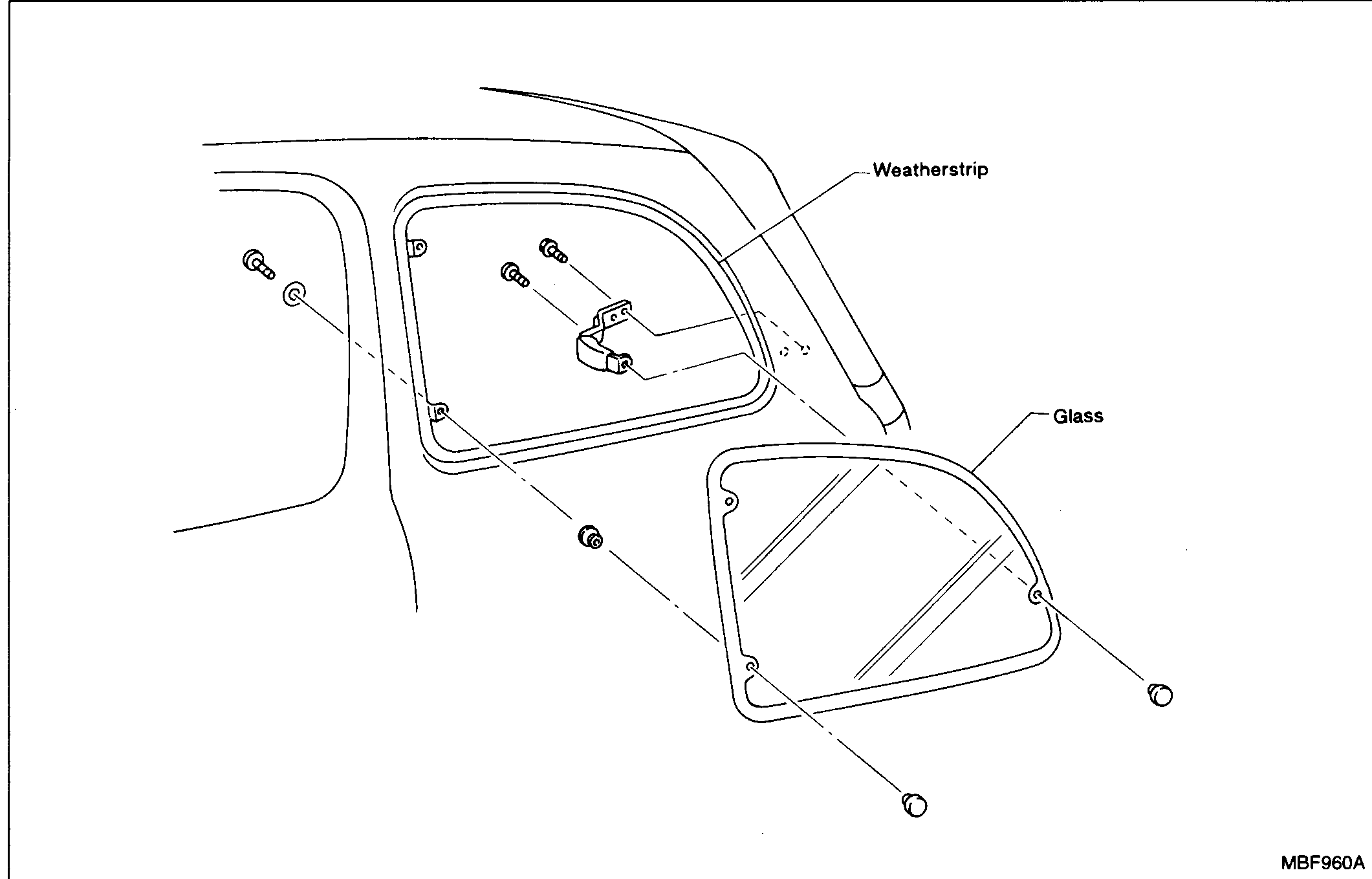
Side Window
BF-48Type-I side window exploded view showing weatherstrip, glass, and mounting fasteners
Side Window
BF-48Type-I side window exploded view showing weatherstrip, glass, and mounting fasteners
Rear Air Spoiler
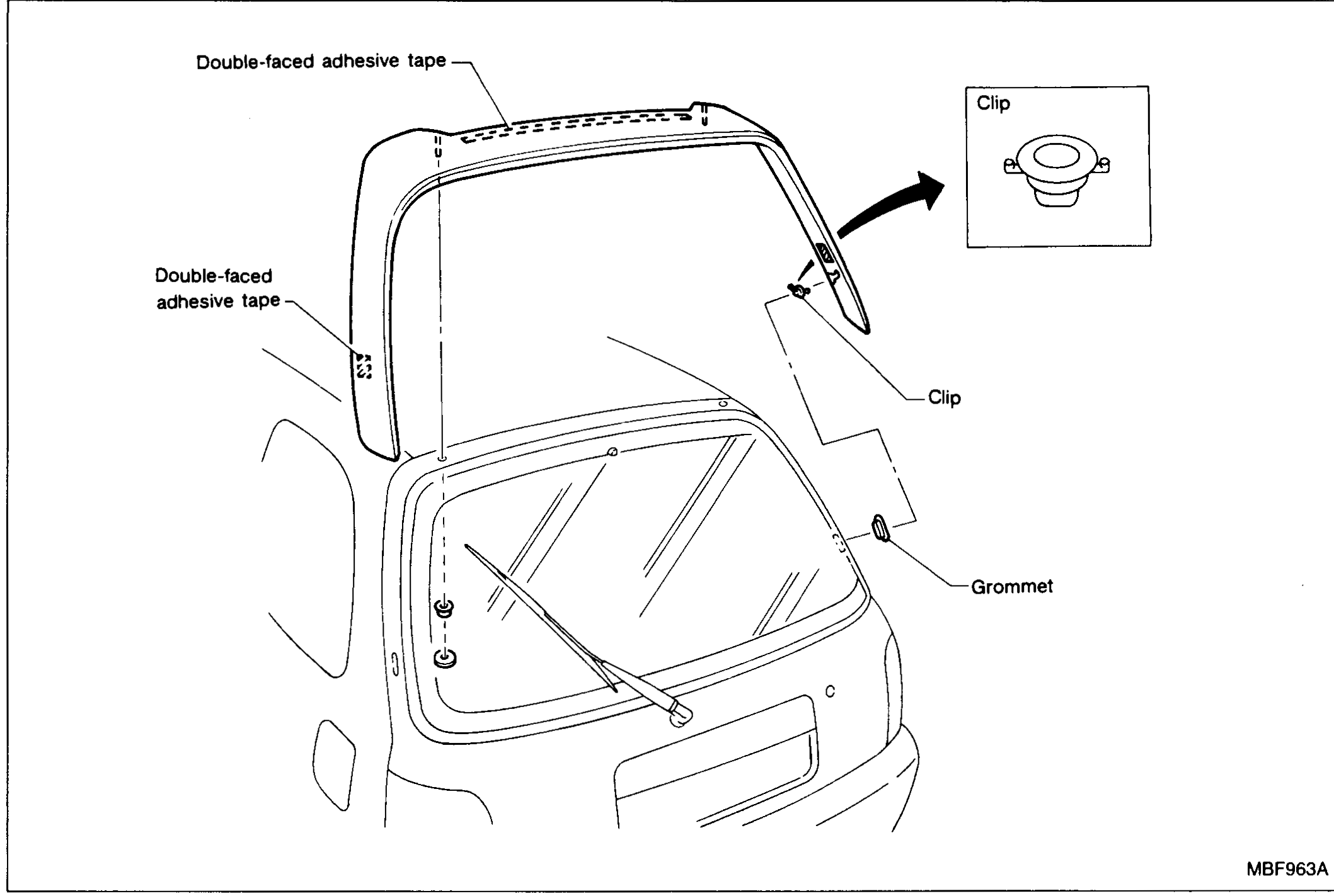
BF-51Rear air spoiler installation on hatchback rear glass area showing double-faced adhesive tape locations, clip detail, and grommet
SUPPLEMENTAL RESTRAINT SYSTEM (SRS) — Removal — Air Bag Module and Spiral Cable
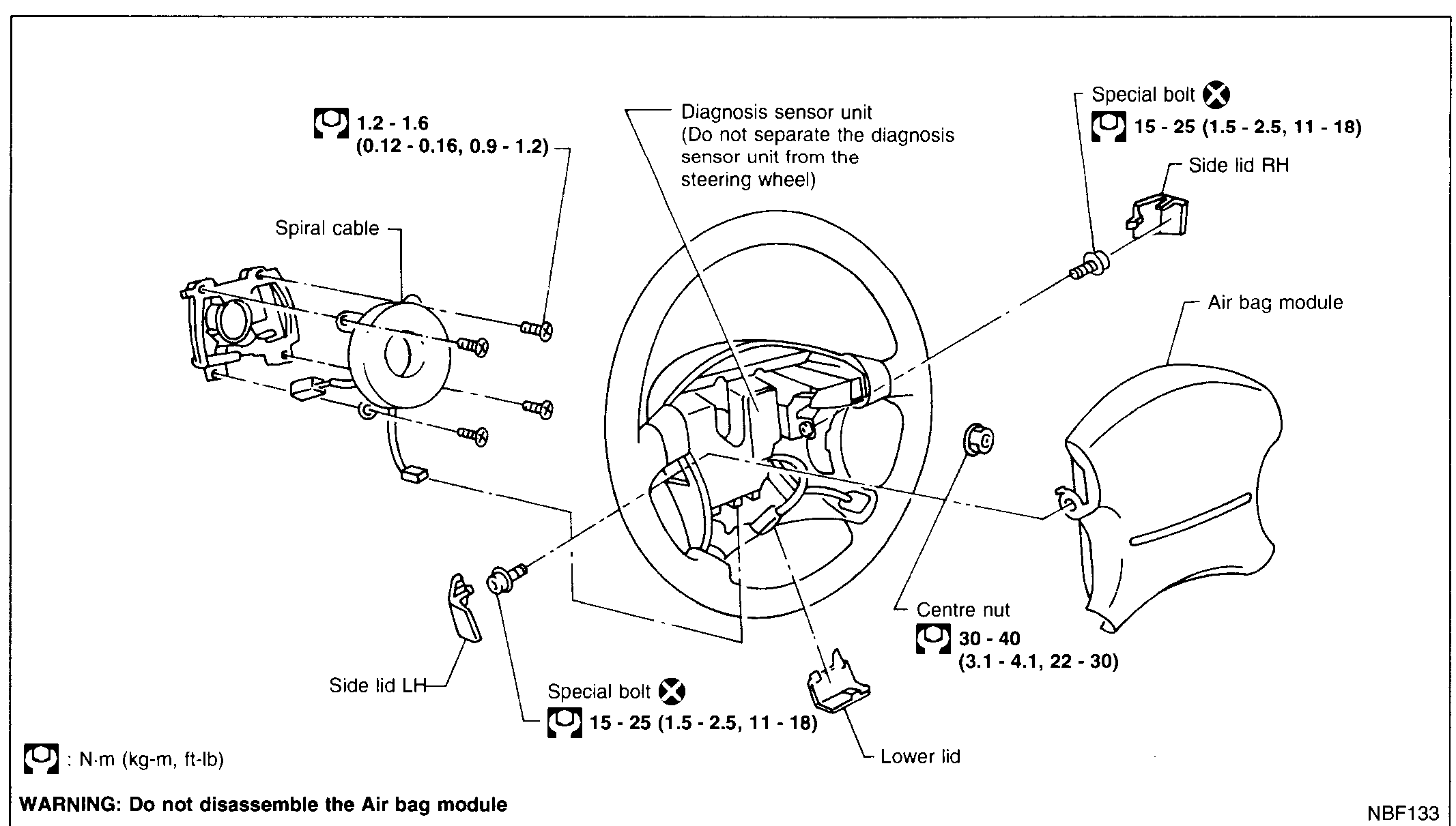
BF-2006Exploded view of the K11 steering wheel and SRS airbag assembly. Components called out: Spiral cable, Diagnosis sensor unit (do not separate from steering wheel), Side lid RH/LH, Special bolts (×, 15-25 N·m), Centre nut (30-40 N·m), Air bag module, Lower lid. Spiral cable mounting bolts torque to 1.2-1.6 N·m.
SEAT - Front Seat
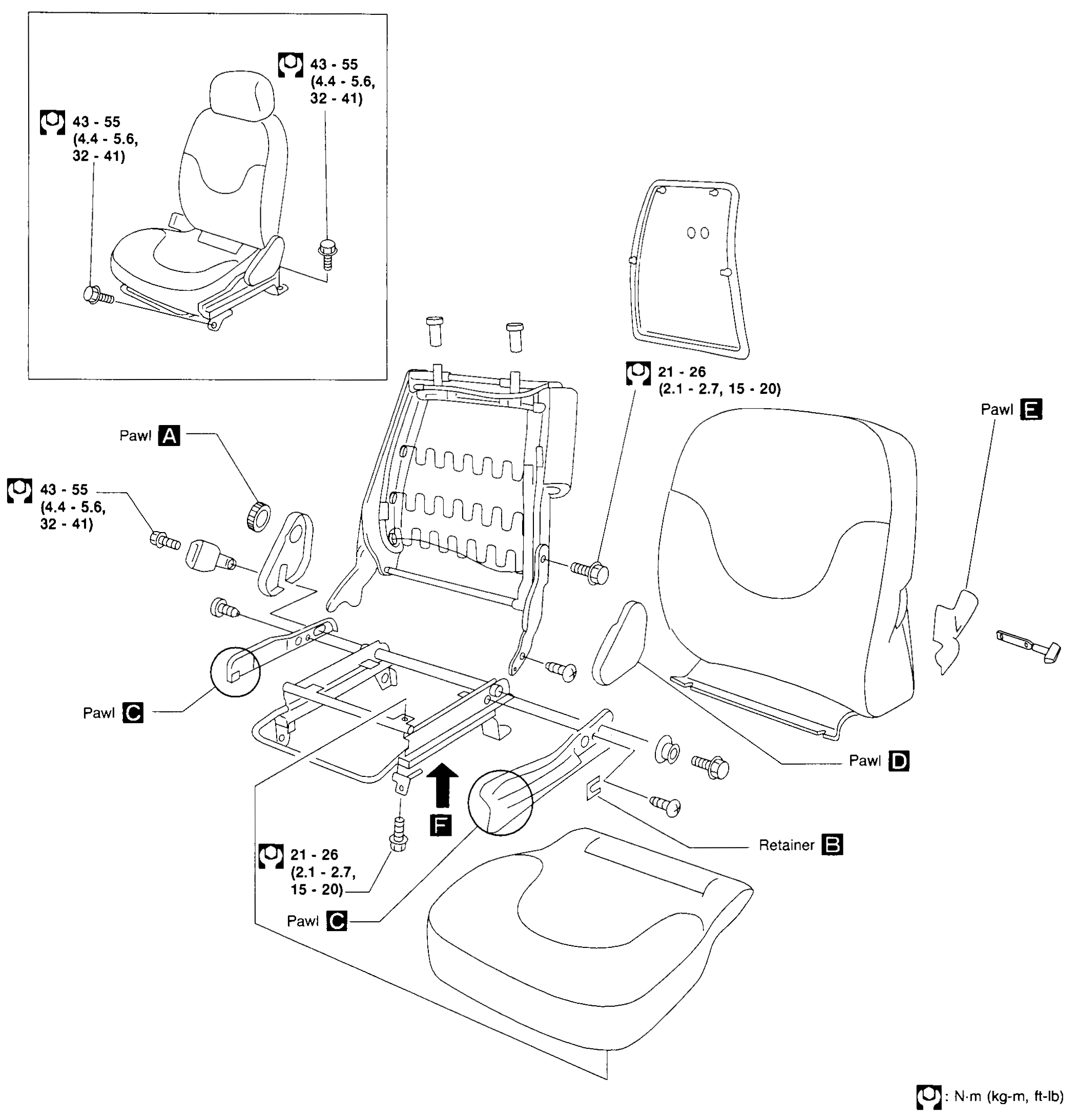
BF-6002Exploded view of the K11 front seat. Inset (top-left) shows the assembled seat with body-mount bolt callouts. Main diagram shows the seat back frame, seat cushion frame, side cover, reclining mechanism and headrest exploded outward. Pawl callouts A (reclining adjuster), B (retainer), C (front floor pawl, x2), D (side cover lower pawl), E (seat-back side cover pawl) and F (slide-rail lock release) are labeled. Torque callouts: 43-55 N·m (4.4-5.6 kg-m, 32-41 ft-lb) at the body floor bolts and reclining adjuster; 21-26 N·m (2.1-2.7, 15-20) at the slide-rail fasteners.
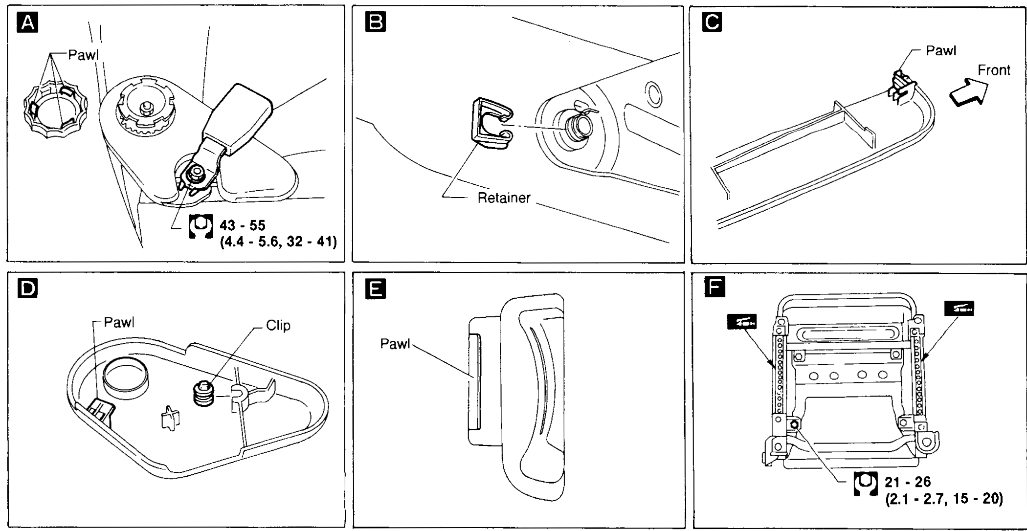
SEAT - Front Seat (Cont'd)
BF-6003Six detail panels labeled A-F: A) reclining-adjuster hand wheel/pawl with body bolt torque 43-55 N·m (4.4-5.6, 32-41). B) Slide-rail retainer clip on rear floor stud. C) Seat-back side-cover lower edge with pawl indicated, arrow marked 'Front'. D) Side cover inner side showing pawl and clip. E) Side cover pawl detail (front view). F) Slide-rail assembly underside with two pawl arrows (front and rear) and torque 21-26 N·m (2.1-2.7, 15-20) at lock bolt.
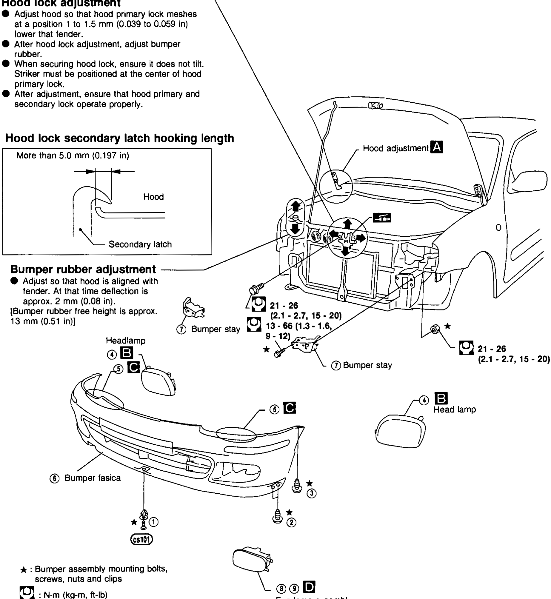
BODY END — Body Front End (Cont'd) — Hood lock and bumper rubber adjustment / Front bumper assembly exploded view
BF-7004Exploded view of the K11 front end. Top: three-quarter front view of the car body showing the hood, hood-lock area, fender, and headlamp. Annotations point to 'Hood adjustment (A)' at hinge, 'Bumper stay' fasteners with torque '21 - 26 N·m (2.1 - 2.7, 15 - 20)' and '13 - 16 N·m (1.3 - 1.6, 9 - 12)' for screws/nuts/clips. Two boxed insets on left: 'Hood lock adjustment' (with bullet points) and 'Hood lock secondary latch hooking length' (showing 'More than 5.0 mm (0.197 in)' between hood and secondary latch). 'Bumper rubber adjustment' inset notes 'approx. 2 mm (0.08 in)' deflection; bumper rubber free height approx. 13 mm (0.51 in). Bottom: exploded view of bumper fascia, headlamp, fog lamp assembly, and bumper stay with leader lines from each part to its mounting position. Legend: ★ bumper assembly mounting bolts, screws, nuts and clips; torque symbol N·m (kg-m, ft-lb).
Heater & Air Conditioner
HA2 diagrams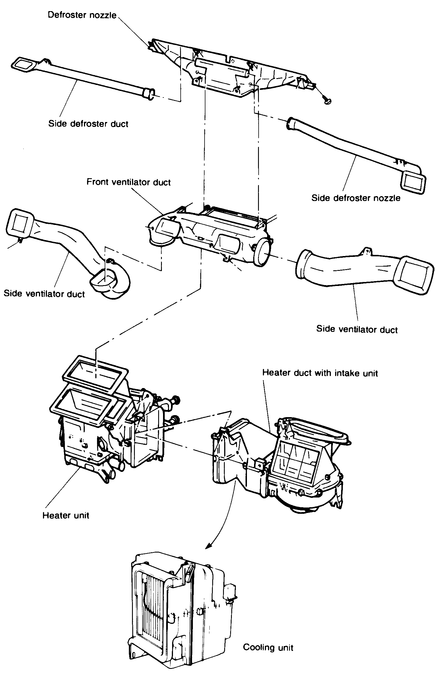
DESCRIPTION — Overall System — Component Layout
HA-6Exploded view of the HVAC duct work and HVAC units. Top: defroster nozzle with two side-defroster ducts and the side-defroster nozzles. Middle: front ventilator duct in the centre with side-ventilator ducts on left and right. Below: heater unit on the left and heater duct with intake unit on the right, with the cooling unit at the bottom-centre.
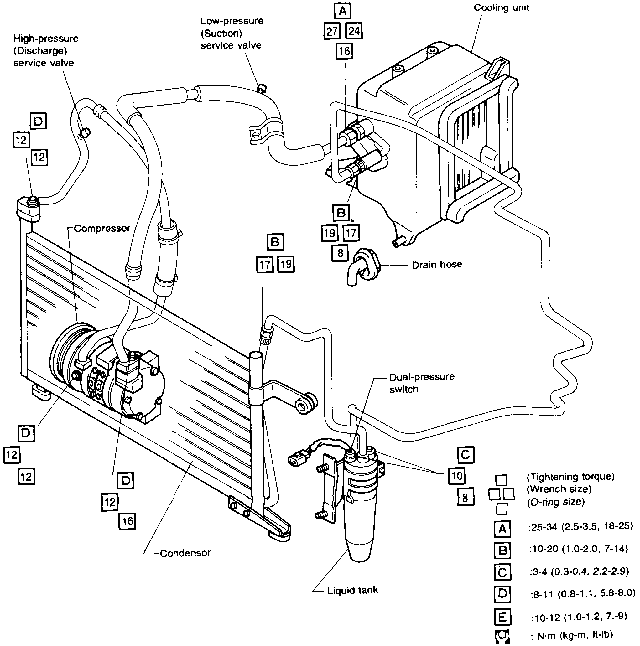
SERVICE PROCEDURES — Refrigerant Lines
HA-25Electrical System
EL14 diagrams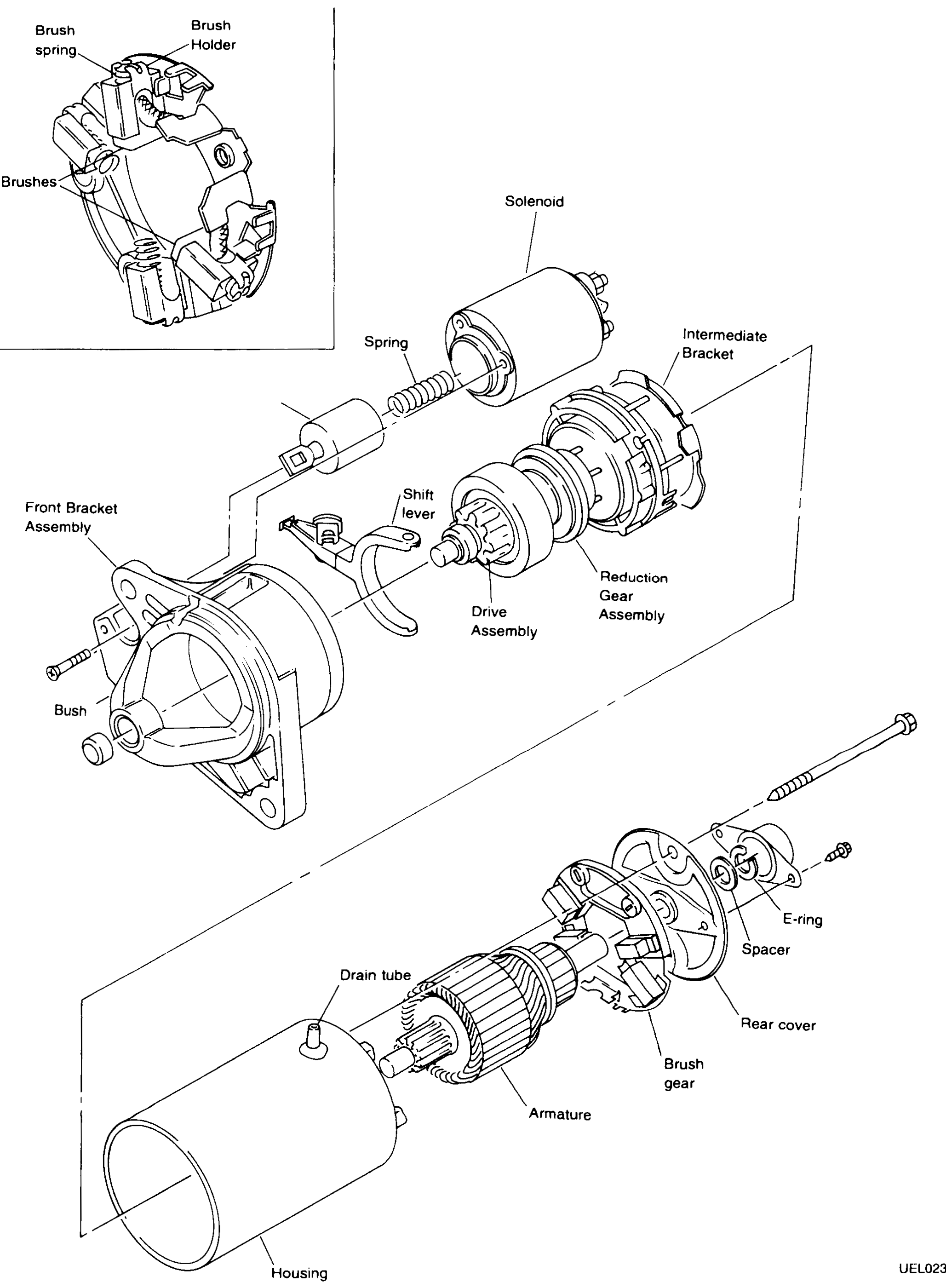
Starting System - Starter - Construction - Bosch
EL-26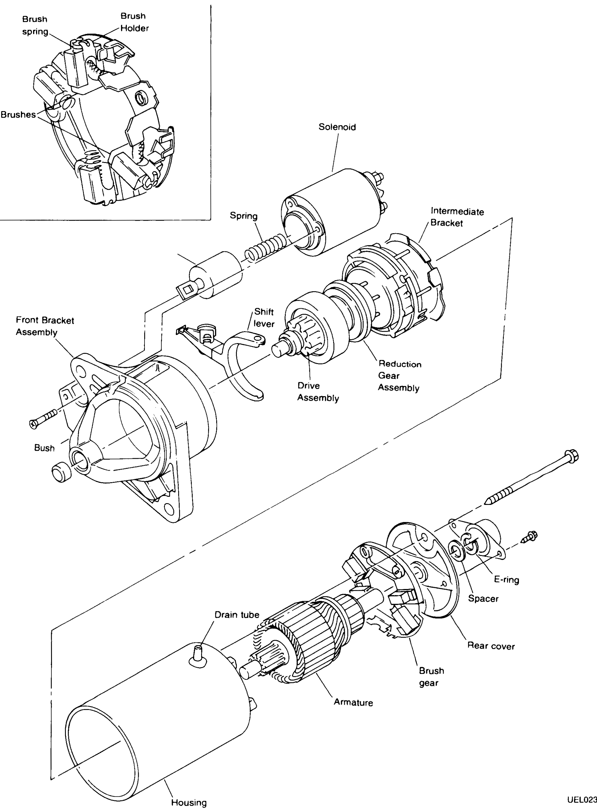
STARTING SYSTEM — Starter — Construction — Bosch
EL-26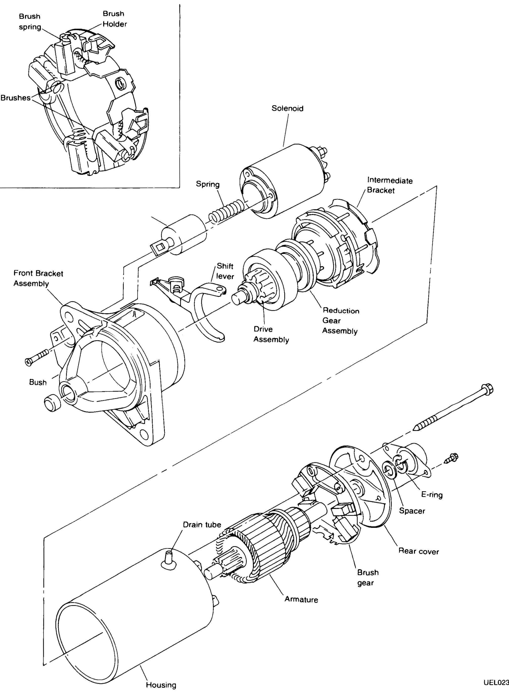
STARTING SYSTEM — Starter — Construction — Bosch (Base K11)
EL-26Exploded view of the Bosch starter motor. Front bracket assembly (with bush), shift lever, drive (pinion) assembly, reduction gear assembly, intermediate bracket, solenoid (with spring), armature, brush gear, rear cover, spacer, E-ring, housing, drain tube, through-bolt. Inset (top-left) details the brush holder with brush spring + brushes.
Charging System - Alternator - Construction
EL-35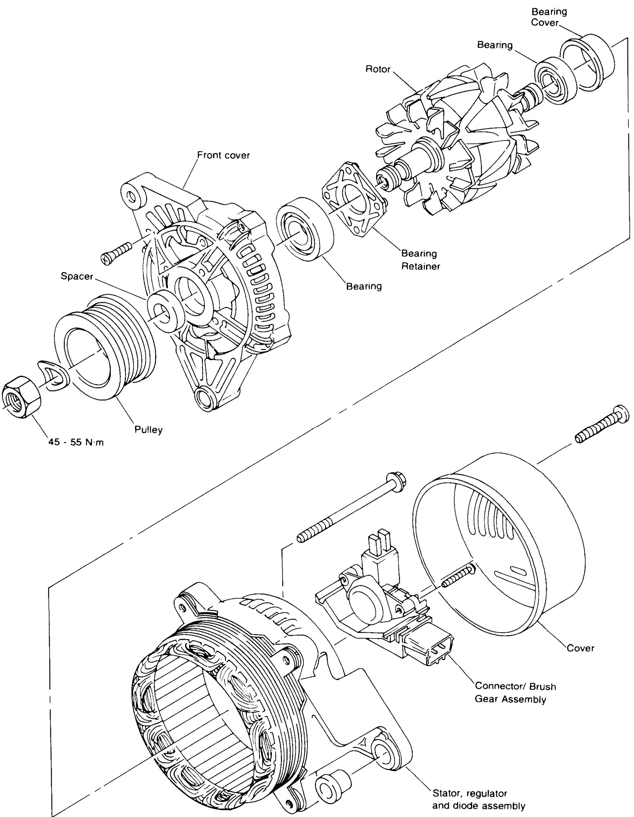
CHARGING SYSTEM — Alternator — Construction
EL-35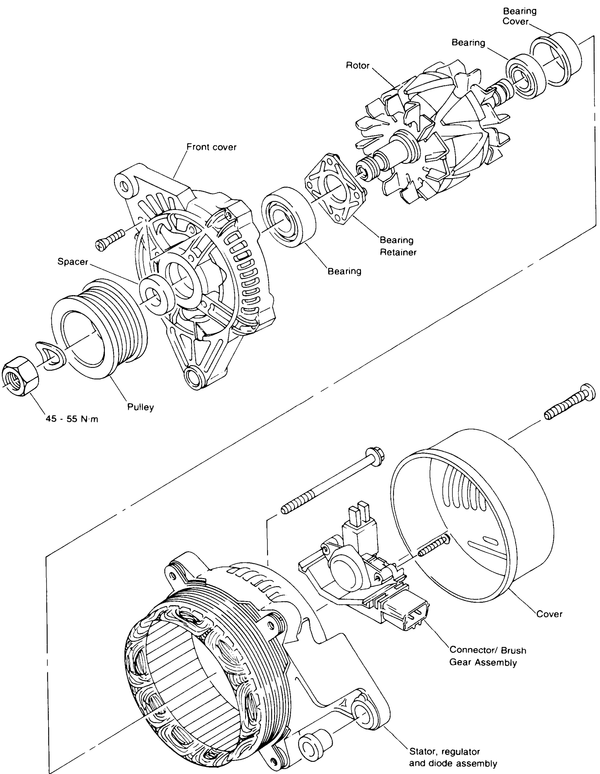
CHARGING SYSTEM — Alternator — Construction (Base K11)
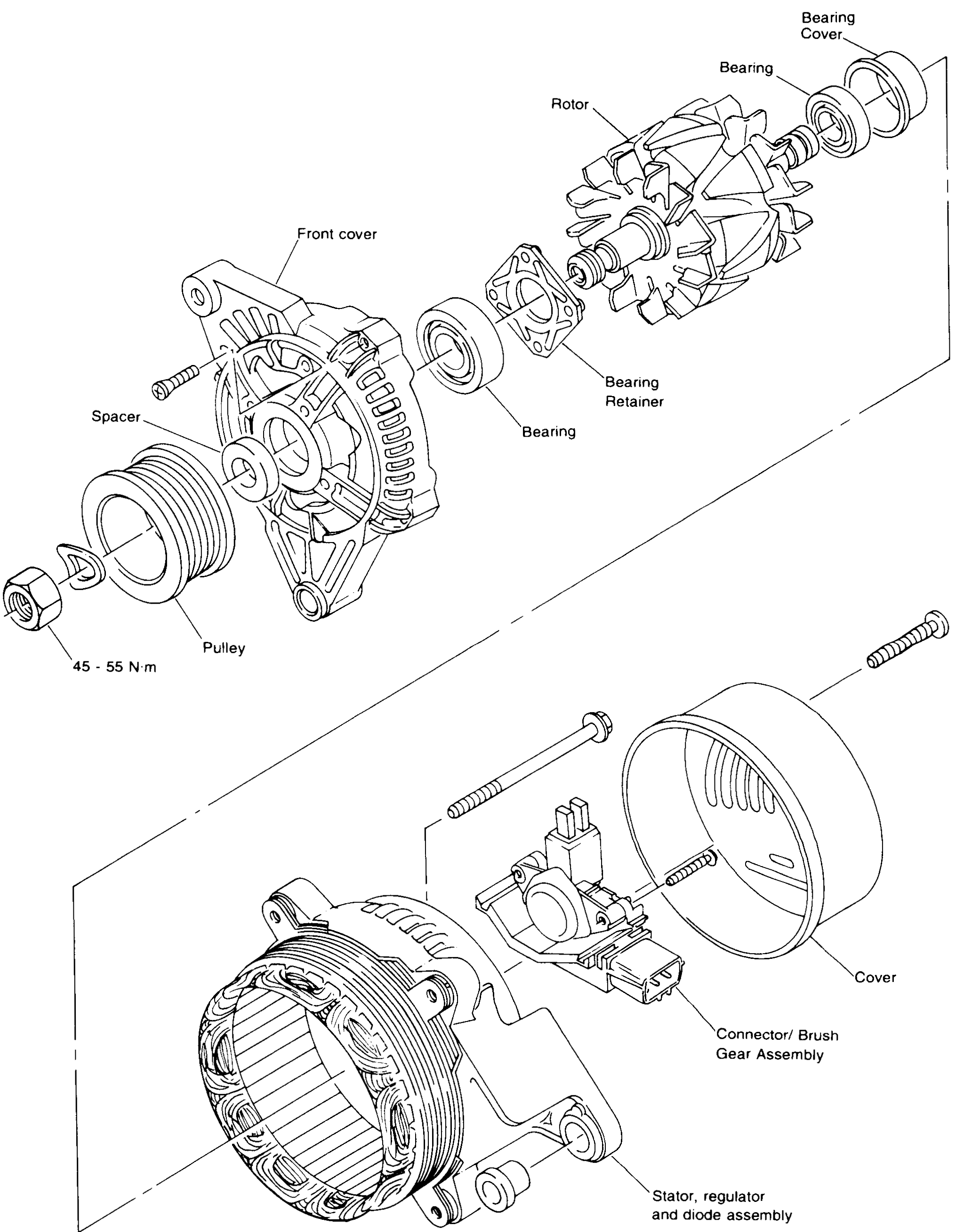
EL-35Exploded view of the alternator. Pulley (nut torque 45-55 N·m), spacer, front cover, front bearing, bearing retainer, rotor, rear bearing + bearing cover, stator/regulator/diode assembly, connector/brush gear assembly, rear cover with through-bolts.
METER AND GAUGES — Combination Meter
EL-84
METER AND GAUGES — Instrument Pack — Disassembly / Installation
EL-87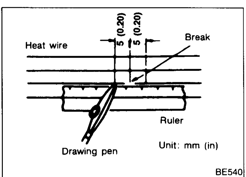
REAR WINDOW DEFOGGER — Filament Repair
EL-119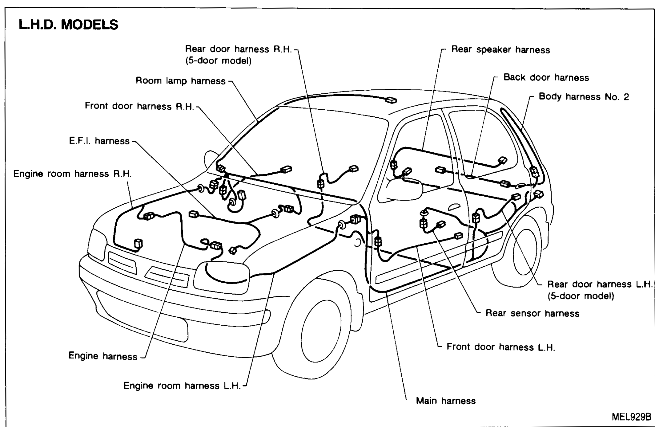
HARNESS LAYOUT — Outline — L.H.D. and R.H.D. Models
EL-127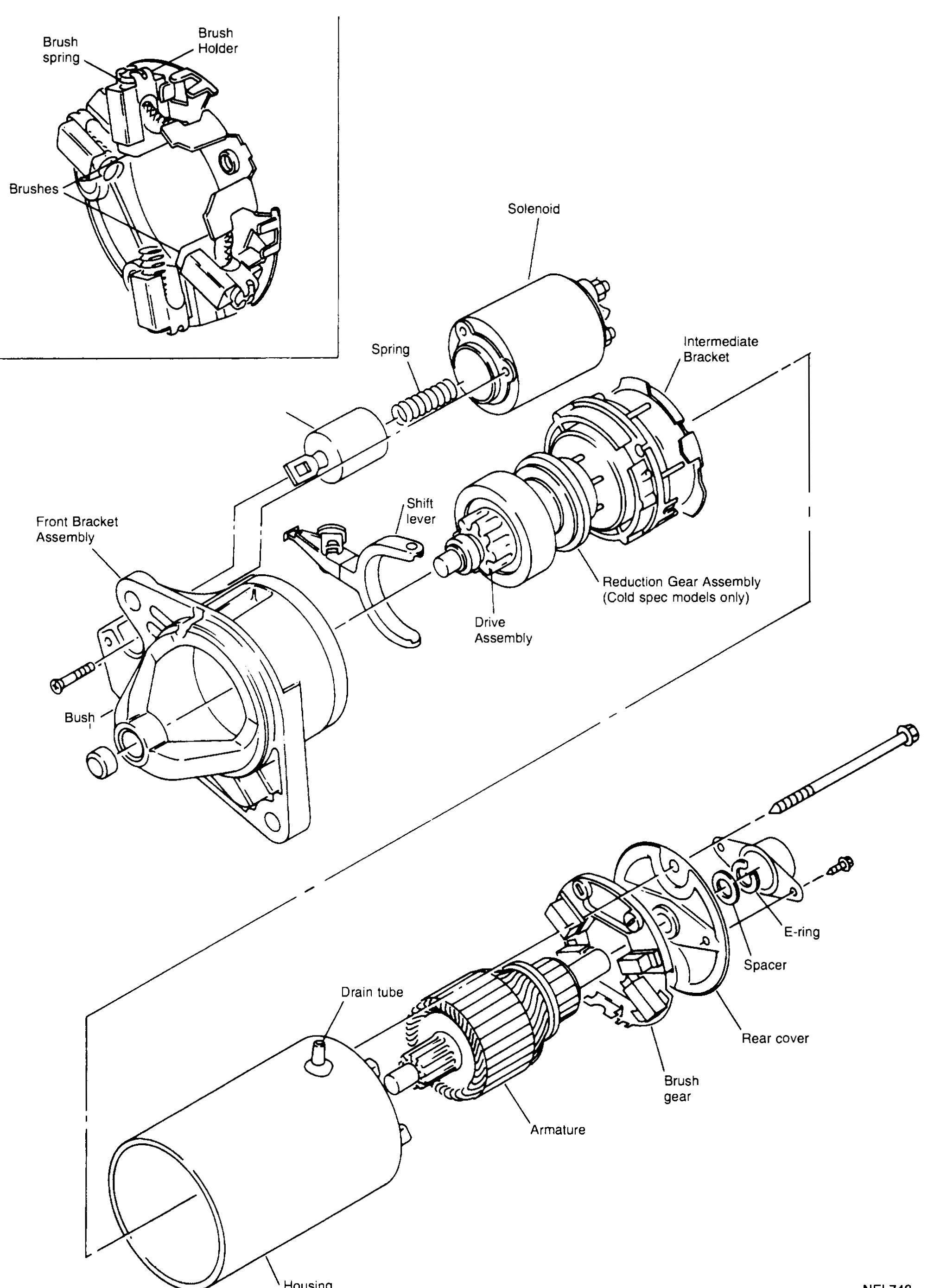
STARTING SYSTEM - Starter - Construction - Bosch
EL-7006Bosch starter motor exploded view
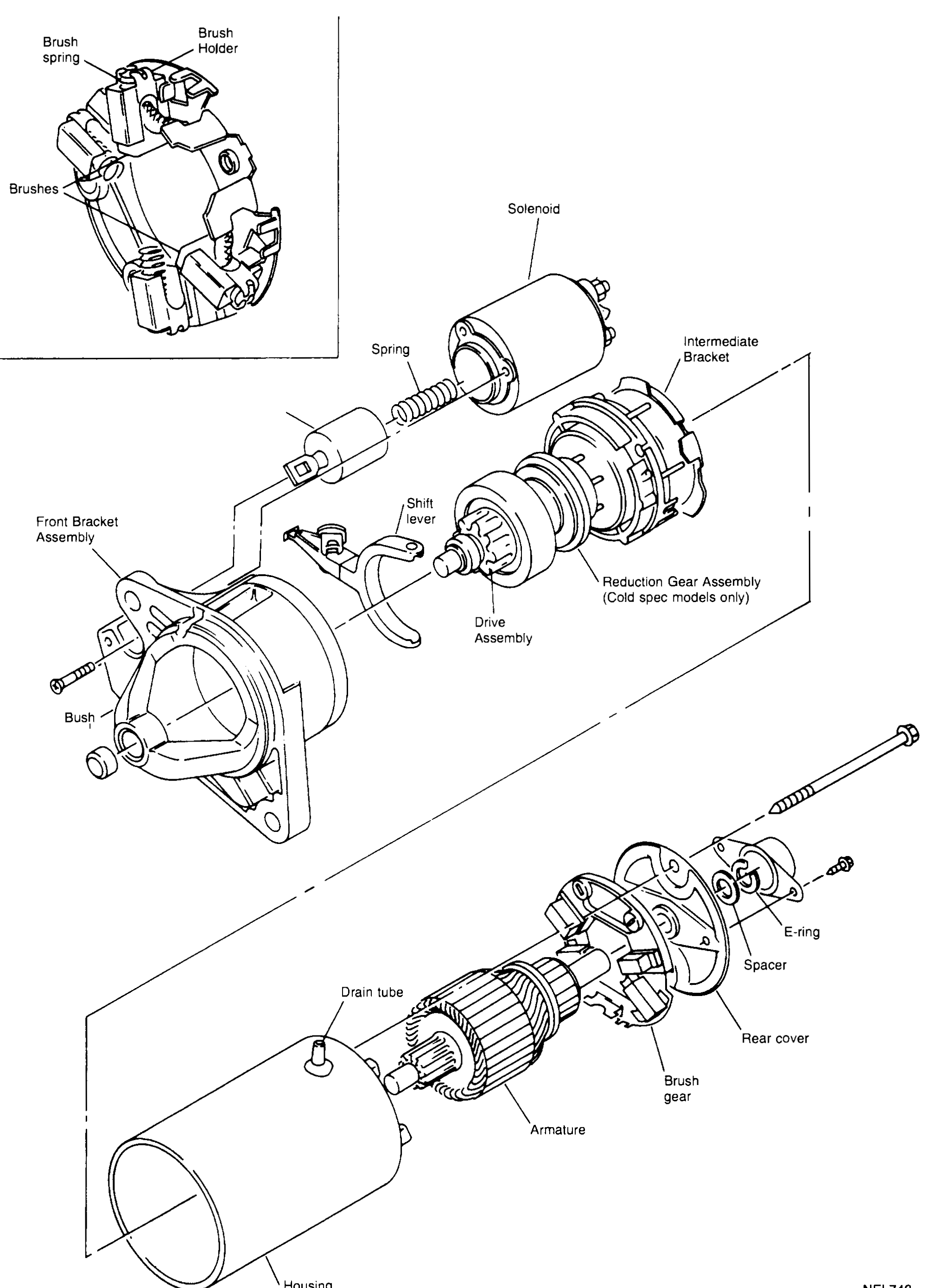
STARTING SYSTEM — Starter — Construction — Bosch (Supplement-VII)
EL-7006Exploded view of the Bosch starter motor. Three subgroup illustrations: (1) Brush holder detail — Brush spring, Brush Holder, Brushes. (2) Front bracket / solenoid / drive subassembly — Front Bracket Assembly, Bush, Solenoid, Spring, Shift lever, Drive Assembly, Intermediate Bracket, Reduction Gear Assembly (Cold spec models only). (3) Motor body — Drain tube, Housing, Armature, Brush gear, Rear cover, Spacer, E-ring + tie-bolt.
CHARGING SYSTEM - ALTERNATOR - Construction
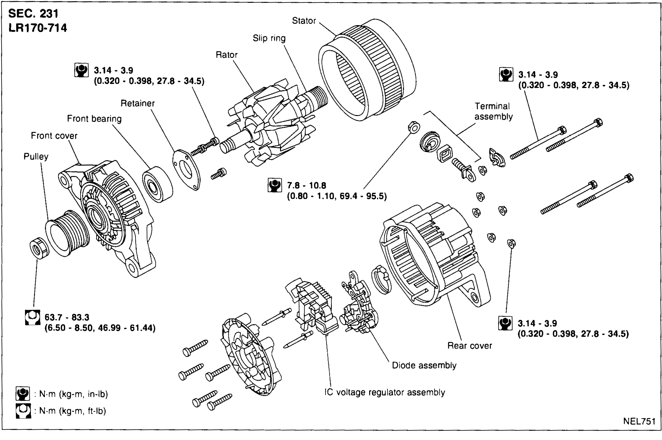
EL-7009Alternator LR170-714 exploded view
CHARGING SYSTEM — ALTERNATOR — Construction (Supplement-VII)
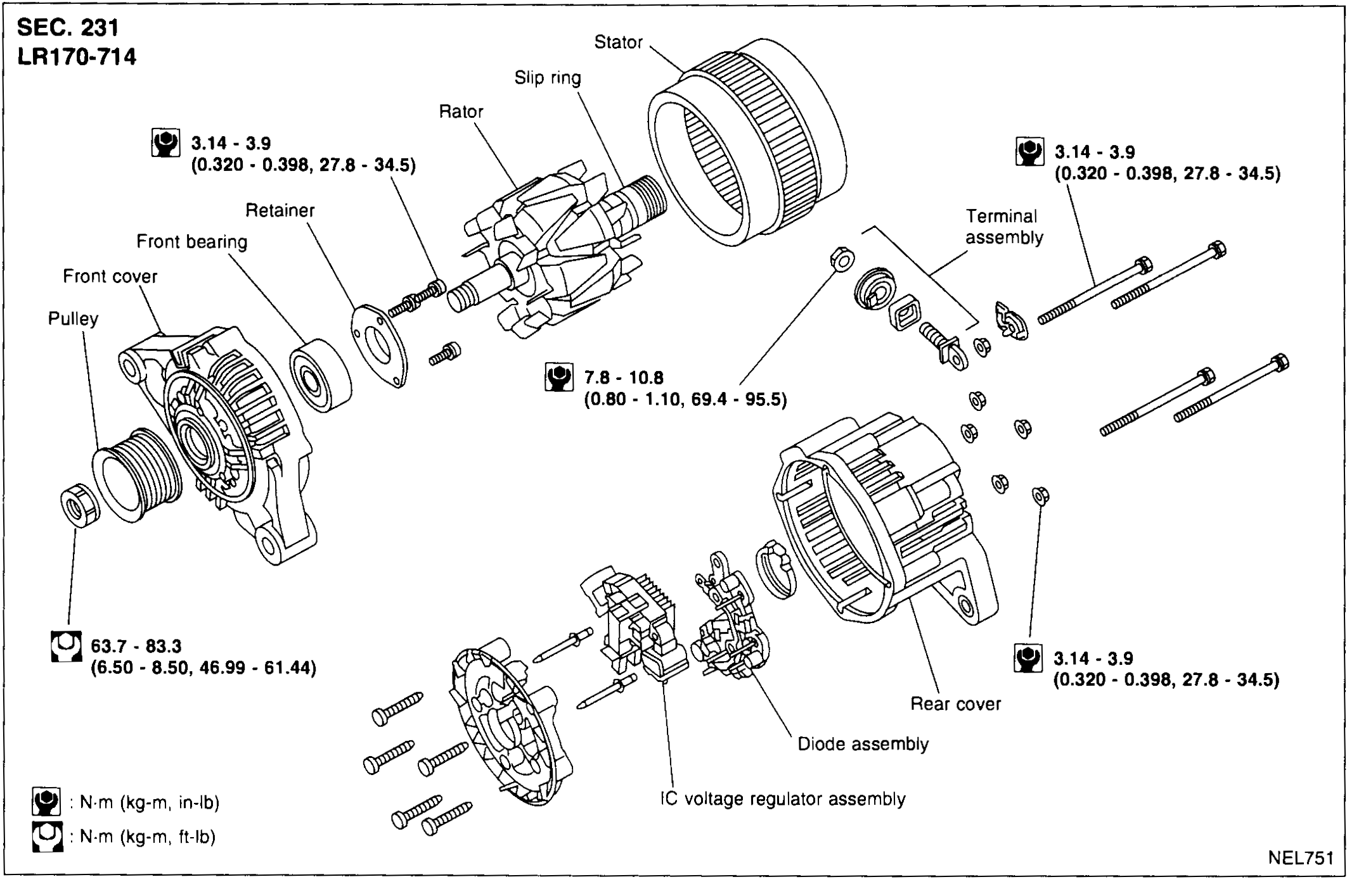
EL-7009Exploded view of the LR170-714 alternator (Section 231). Parts left→right: Pulley, Front cover, Front bearing, Retainer, Rotor with Slip ring, Stator, Diode assembly, IC voltage regulator assembly, Rear cover, Terminal assembly, tie-bolts. Torque values per fastener type are stamped at three points.