
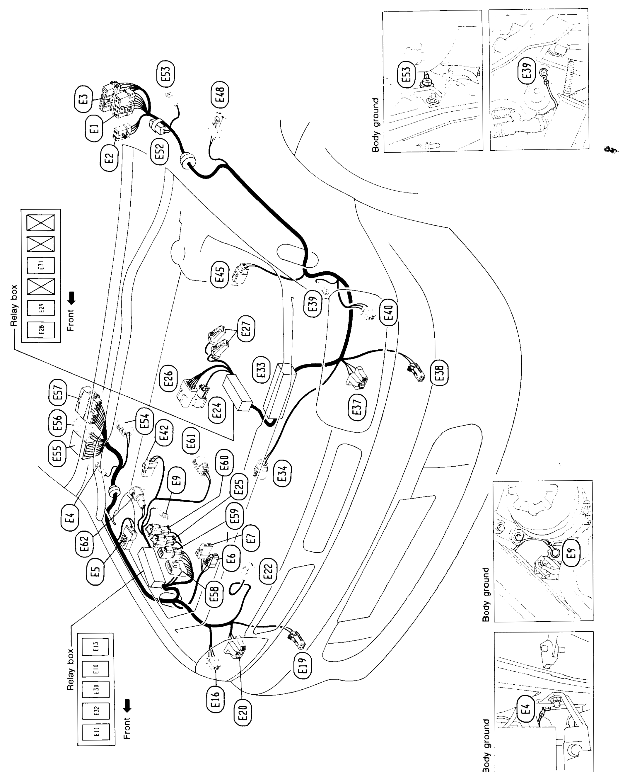
Harness Layout - Engine Room Harness (Cont'd) (R.H.D. Models)
EL-130component photoUnverifiedR.H.D. MODELS. Engine room harness connector location chart, mirror of L.H.D. layout on EL-128. Connector positions are approximate due to dense overlapping bubbles in the original.
Engine Room Harness (Cont'd)
R.H.D. MODELS
Component LocationFig. fig1
Engine room harness layout (R.H.D.) showing routing and the location of connectors E1 through E62, two relay boxes (upper positions E28-E31, lower positions E10-E13) and body-ground points (E4, E9, E39, E53).
MEL918B
1Relay box (upper)(Left of engine bay; positions E28-E31)
2Relay box (lower)(Lower left; positions E10-E13)
3Connectors E1-E62(Distributed across engine bay along harness route)
4Body ground(Inset photos: E53, E39, E9, E4)