
LOCATION OF ELECTRICAL UNITS - Engine Compartment
EL-123component photoRelay box positions and relay assignments differ between L.H.D. and R.H.D. models, and wiper motor/amplifier mount on opposite cowl sides per drive side.
Engine Compartment
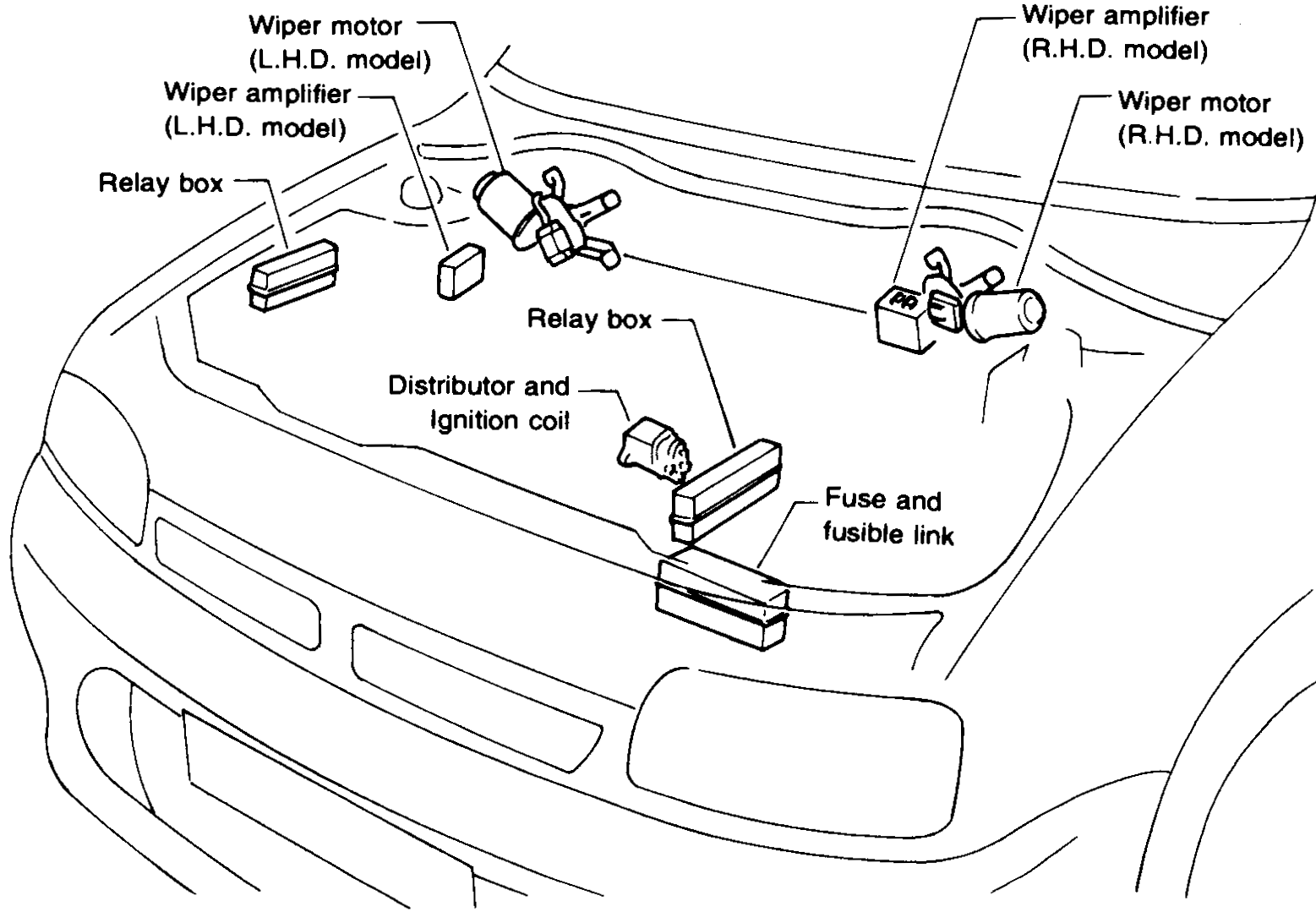
Component LocationFig. fig1
Engine compartment electrical unit locations.
NEL001
1Wiper motor (L.H.D. model)(Left cowl)
2Wiper amplifier (L.H.D. model)(Left cowl)
3Wiper amplifier (R.H.D. model)(Right cowl)
4Wiper motor (R.H.D. model)(Right cowl)
5Relay box(Left and centre of engine bay)
6Distributor and Ignition coil(Centre)
7Fuse and fusible link(Centre)
Component LocationFig. fig2
Left relay box - relay positions (L.H.D. / R.H.D. differ).
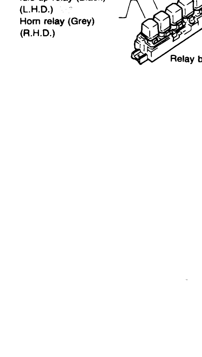
1Rear defogger relay (black) (L.H.D.)(Relay box position 1)
2Front fog relay (Black) (R.H.D.)(Relay box position 1)
3Front Fog/Driving lamp relay (Black) (L.H.D.)(Relay box position 2)
4Idle up relay (Black) (R.H.D.)(Relay box position 2)
5Aircon relay (Brown) (L.H.D.)(Relay box position 3)
6Inhibit relay (Black) (R.H.D.)(Relay box position 3)
7Horn relay (Grey) (L.H.D.)(Relay box position 4)
8Rear fog relay (Black) (R.H.D.)(Relay box position 4)
9Idle up relay (Black) (L.H.D.)(Relay box position 5)
10Horn relay (Grey) (R.H.D.)(Relay box position 5)
Component LocationFig. fig3
Centre relay box - relay positions (L.H.D. / R.H.D. differ).
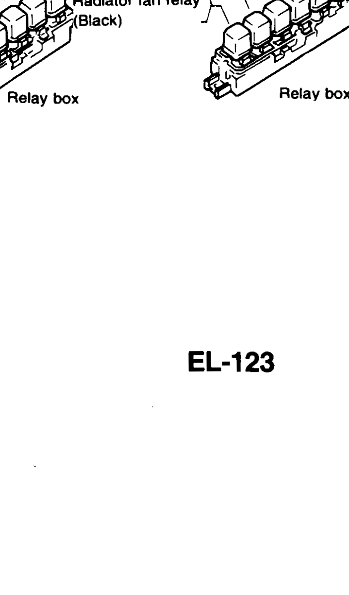
1Rear fog relay (Black) (L.H.D.)(Relay box position 1)
2Spare relay (R.H.D.)(Relay box position 1)
3Spare relay (L.H.D.)(Relay box position 2)
4Radiator fan relay (Black) (R.H.D.)(Relay box position 2)
5N-CVT relay (Black)(Relay box)
6Inhibit relay (Black) (L.H.D.)(Relay box)
7Spare relay (R.H.D.)(Relay box)
8E.G.I. relay (Green)(Relay box)
9Radiator fan relay (Black)(Relay box)
Component LocationFig. fig4
Fuse and fusible link block.

1Power Supply Fuses(Upper row)
2Fuse links(Lower left)
3Front(Orientation arrow)