
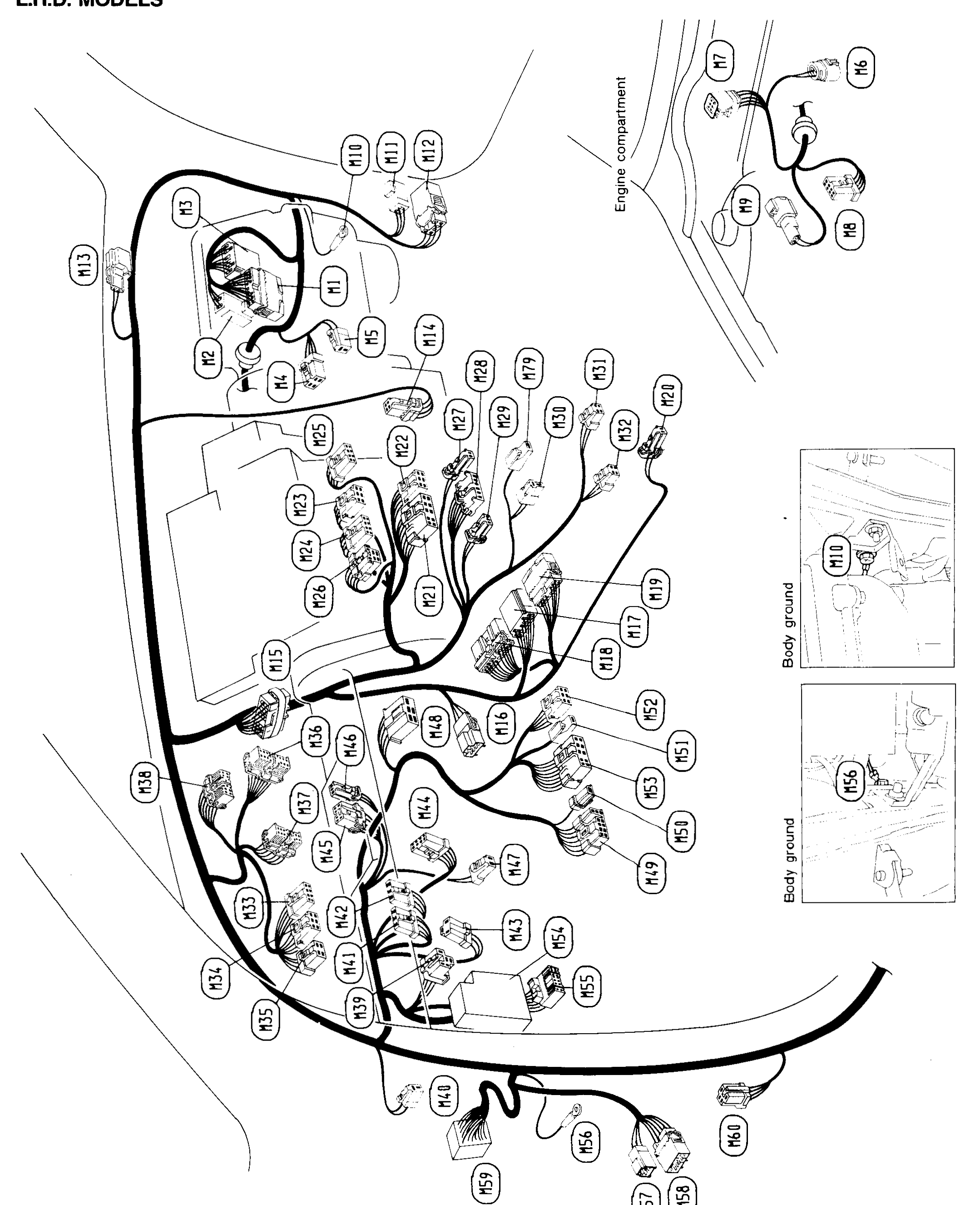
Harness Layout - Main Harness (L.H.D. Models)
EL-132component photoUnverifiedL.H.D. MODELS. Main harness connector location chart. Connector positions are approximate due to dense overlapping bubbles; connectors M39, M40, M50 were not confidently located.
Main Harness
L.H.D. MODELS
Component LocationFig. fig1
Main harness layout (L.H.D.) showing routing through the cabin/dash and the location of connectors M1 through M60, the engine-compartment pass-through (M6-M9) and body-ground points (M10, M55).
MEL921B
1Connectors M1-M60(Distributed across cabin/dash along main harness route)
2Engine compartment(Top-right inset: connectors M6, M7, M8, M9)
3Body ground(Inset photos: M10, M55)