
DTC P0133 Heated Oxygen Sensor 1 (Front) (Response Monitoring) — Component Inspection (CG10, CGA3)
EF & EC-7119flowchartApplies to CG10 and CGA3 engines. Sensor handling — never re-use a sensor that has fallen >0.5 m onto hard surface. ECM pin 12 = HO2S1 front signal. 'HO2S1 MTR (B1)' (printed in step 2) appears to be the same monitor as 'HO2S1 MNTR (B1)' used elsewhere on the page — likely typo.
Component Inspection — HEATED OXYGEN SENSOR 1 (FRONT)
With CONSULT-II
- 1Start engine and warm it up to normal operating temperature.
 SEF646Y
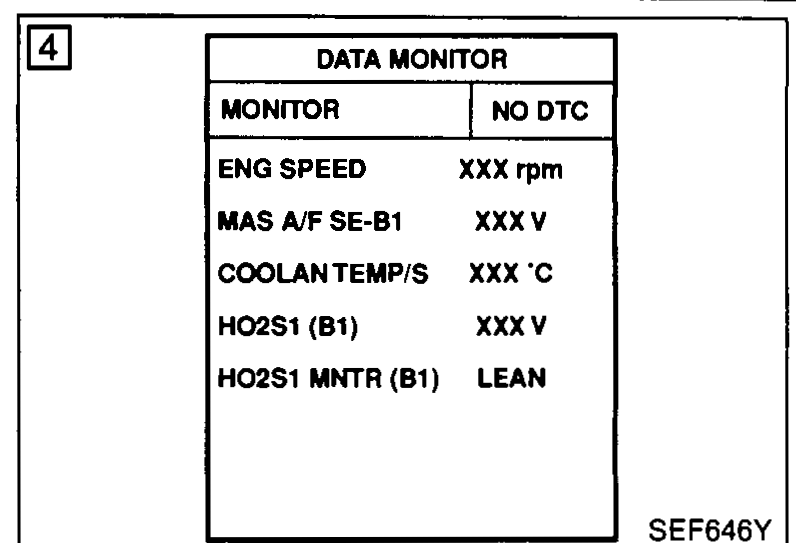
 - 2Select "MANU TRIG" and "HI SPEED" in "DATA MONITOR" mode, and select "HO2S1 MTR (B1)".
- 3Hold engine speed at 2,000 rpm under no load during the following steps.
- 4Touch "RECORD" on CONSULT-II screen.
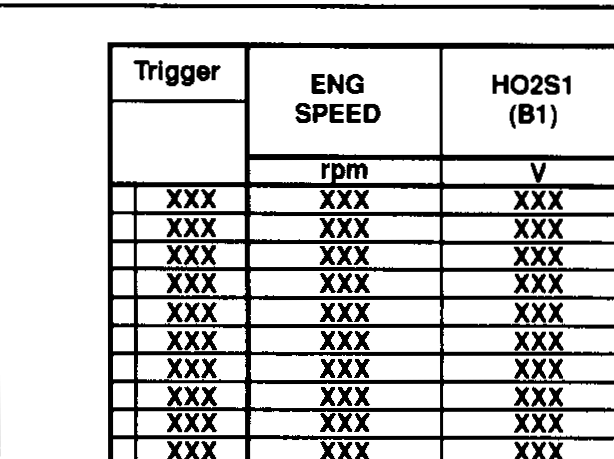
- 5Check the following. • "HO2S1 MNTR (B1)" in "DATA MONITOR" mode changes from "RICH" to "LEAN" to "RICH" 3 times in 10 seconds. 3 times (cycles) are counted as shown below: R = "HO2S1 MNTR (B1)", "RICH"; L = "HO2S1 MNTR (B1)", "LEAN". • "HO2S1 (B1)" voltage goes above 0.6 V at least once. • "HO2S1 (B1)" voltage goes below 0.3 V at least once. • "HO2S1 (B1)" voltage never exceeds 1.08 V.
 SEF217YA
CAUTION
Discard any heated oxygen sensor which has been dropped from a height of more than 0.5 m (19.7 in) onto a hard surface such as a concrete floor; use a new one.
Without CONSULT-II
- 1Start engine and warm it up to normal operating temperature.
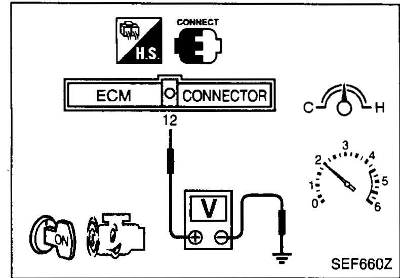
- 2Set voltmeter probes between ECM terminal 12 and ground.
 SEF660Z
 - 3Check the following with engine speed held at 2,000 rpm constant under no load.
- The voltage fluctuates between 0 to 0.3 V and 0.6 to 1.0 V more than three times within 10 seconds.
- 1 time: 0 - 0.3 V → 0.6 - 1.0 V → 0 - 0.3 V.
- 2 times: 0 - 0.3 V → 0.6 - 1.0 V → 0 - 0.3 V → 0.6 - 1.0 V → 0 - 0.3 V.
- The maximum voltage is over 0.6 V at least one time.
- The minimum voltage is below 0.3 V at least one time.
- The voltage never exceeds 1.08 V.
CAUTION
Discard any heated oxygen sensor which has been dropped from a height of more than 0.5 m (19.7 in) onto a hard surface such as a concrete floor; use a new one.