
ENGINE AND EMISSION CONTROL OVERALL SYSTEM — Engine Control Component Parts Location (Cont'd)
EF & EC-7012component photoEngine Control Component Parts Location (Cont'd)
CG10, CGA3
Component LocationFig. fig1
Throttle body and intake area components.
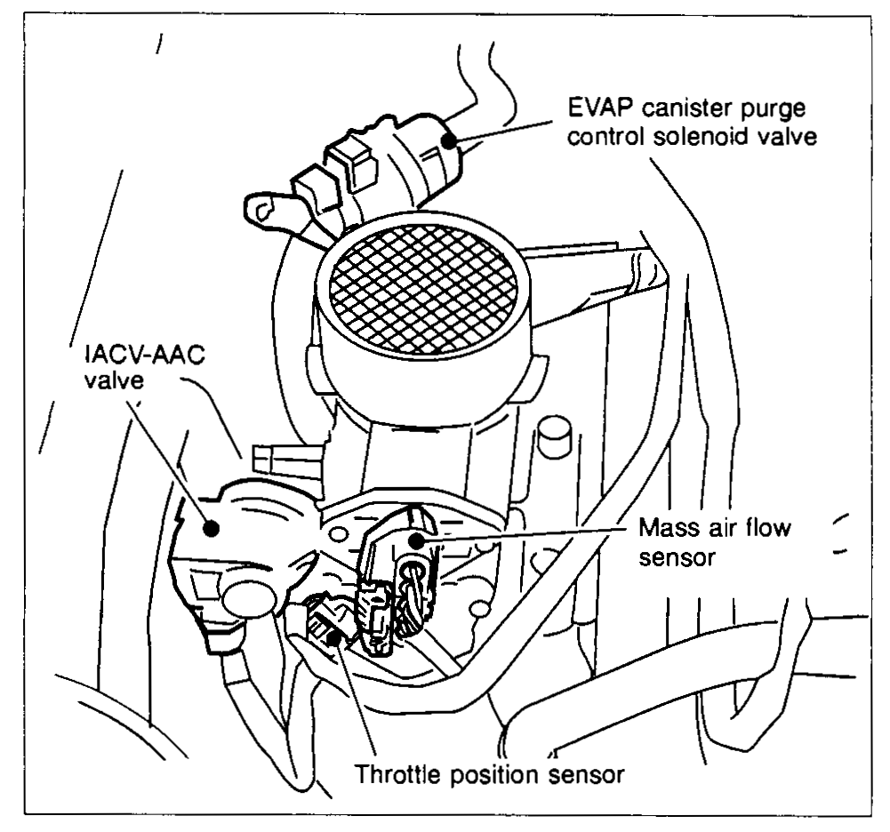
1EVAP canister purge control solenoid valve(top)
2IACV-AAC valve(left)
3Mass air flow sensor(right)
4Throttle position sensor(bottom-center)
Component LocationFig. fig2
Front of engine components.
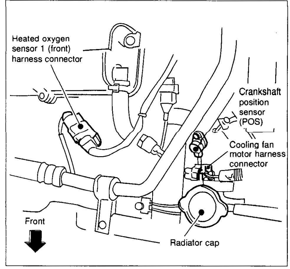
1Heated oxygen sensor 1 (front) harness connector(upper-left)
2Crankshaft position sensor (POS)(right)
3Cooling fan motor harness connector(right)
4Radiator cap(bottom-right)
Component LocationFig. fig3
Camshaft area components.
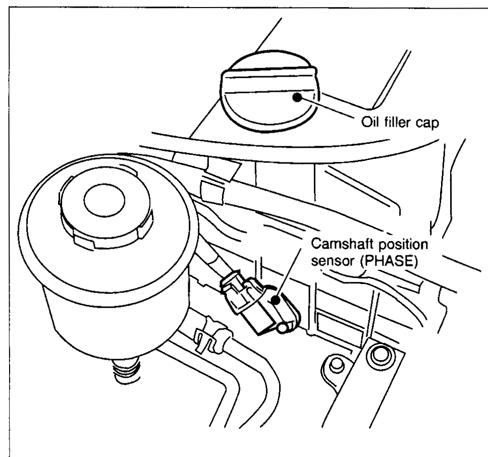
1Oil filler cap(top)
2Camshaft position sensor (PHASE)(right)
Component LocationFig. fig4
Ignition coil and coolant components.
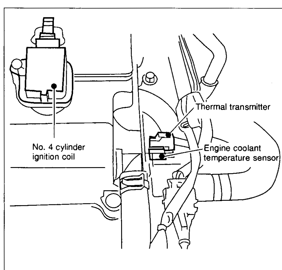
1No. 4 cylinder ignition coil(left)
2Thermal transmitter(top-right)
3Engine coolant temperature sensor(right)
Component LocationFig. fig5
ECM relay near battery.
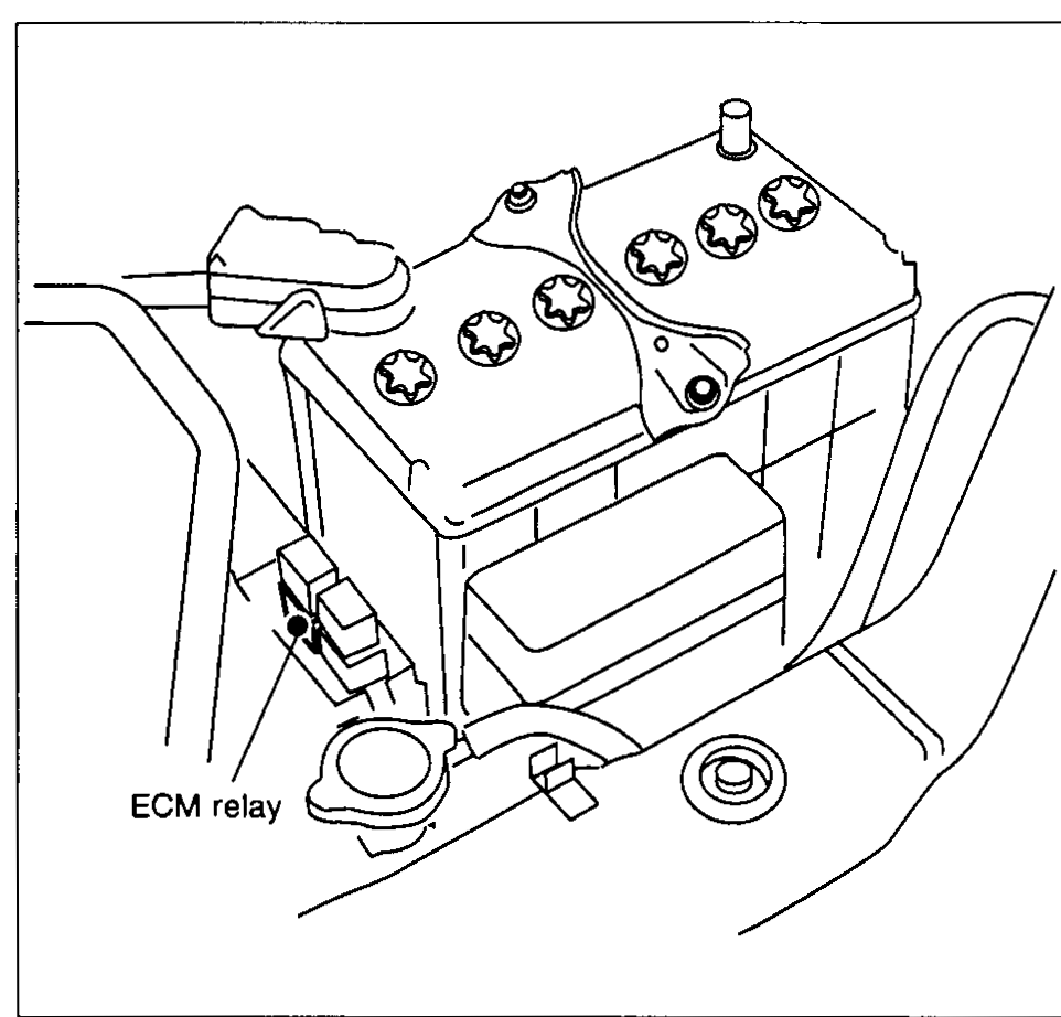
1ECM relay(bottom-left of battery)
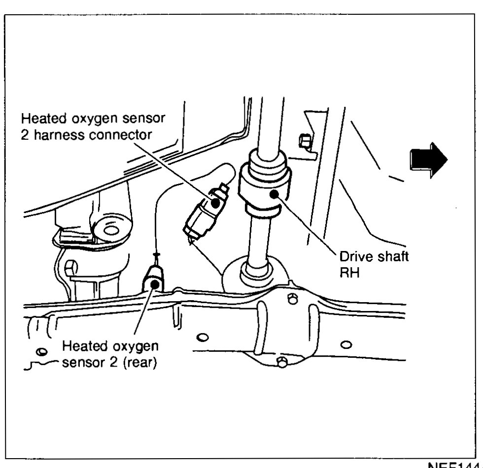
Component LocationFig. fig6
Rear oxygen sensor area near drive shaft.
NEF144A
1Heated oxygen sensor 2 harness connector(upper-left)
2Heated oxygen sensor 2 (rear)(lower-left)
3Drive shaft RH(right)