
ENGINE AND EMISSION CONTROL OVERALL SYSTEM — System Diagram
EF & EC-7015wiring diagramSystem Diagram
CG10, CGA3
Component LocationFig. fig1
Engine and emission control system block diagram showing inputs to and outputs from the ECM.
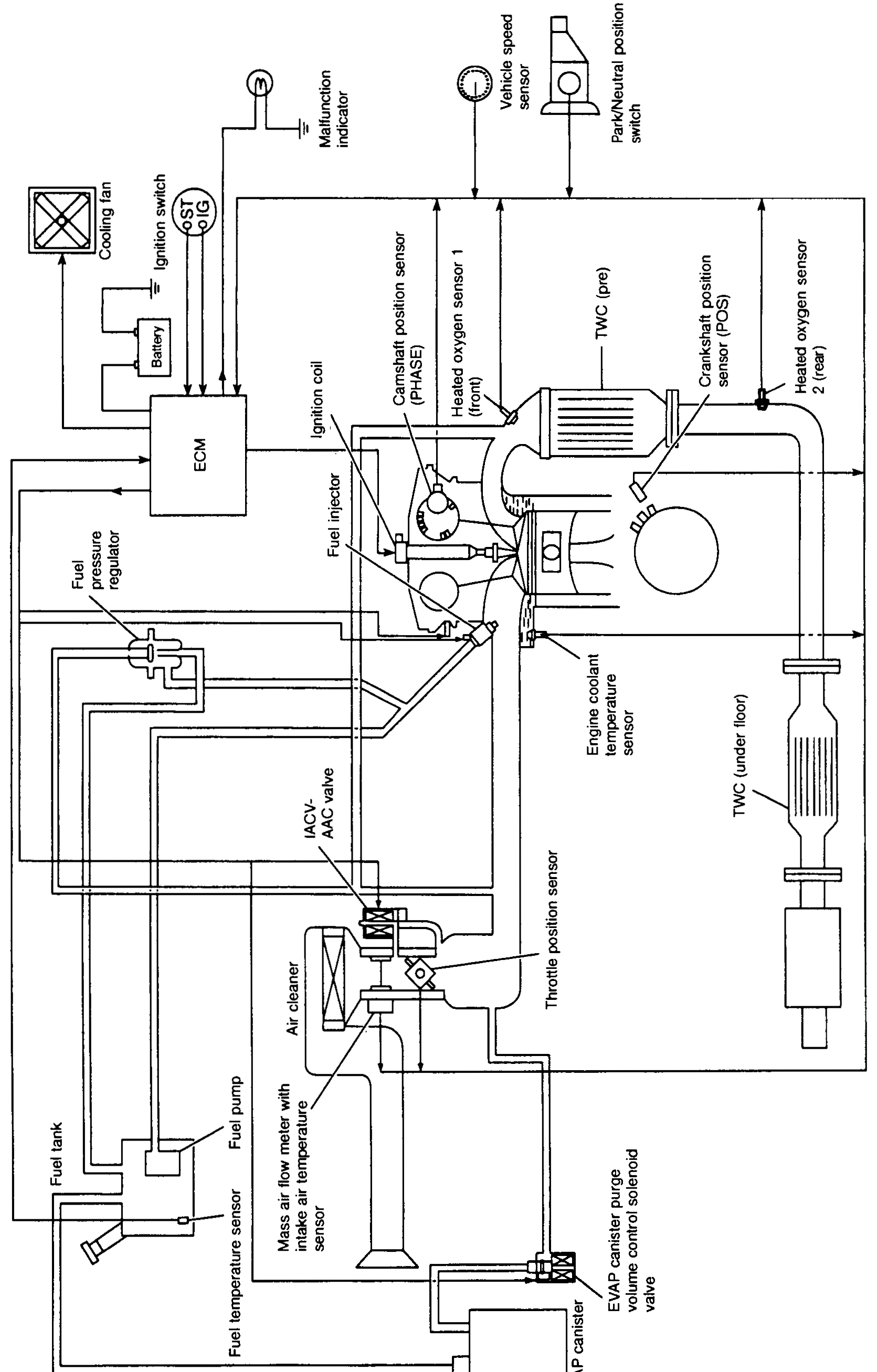
SEF641Z
1ECM(left-center)
2Cooling fan(top-left)
3Ignition switch (ST, IG)(top-left)
4Battery(left)
5Malfunction indicator(top)
6Vehicle speed sensor(top-center)
7Park/Neutral position switch(top-right)
8Camshaft position sensor (PHASE)(top-center)
9Heated oxygen sensor 1 (front)(center-right (on exhaust pre-TWC))
10TWC (pre)(center-right (exhaust))
11Crankshaft position sensor (POS)(right)
12Heated oxygen sensor 2 (rear)(right)
13TWC (under floor)(right (exhaust))
14Ignition coil(center)
15Fuel injector(center)
16Fuel pressure regulator(left-center)
17IACV-AAC valve(center-bottom)
18Air cleaner(bottom-center)
19Throttle position sensor(center)
20Engine coolant temperature sensor(center-right)
21Mass air flow meter with intake air temperature sensor(bottom-center)
22Fuel pump(bottom-left)
23Fuel temperature sensor(bottom-left)
24Fuel tank(bottom-left)
25EVAP canister(bottom-center)
26EVAP canister purge volume control solenoid valve(bottom-center)