
OUTER COMPONENT PARTS — Intake Manifold & Fuel System (Cont'd) / Fuel Rail Removal & Inspection
EM-9prose procedureIntake Manifold & Fuel System (Cont'd)
Parts Diagram
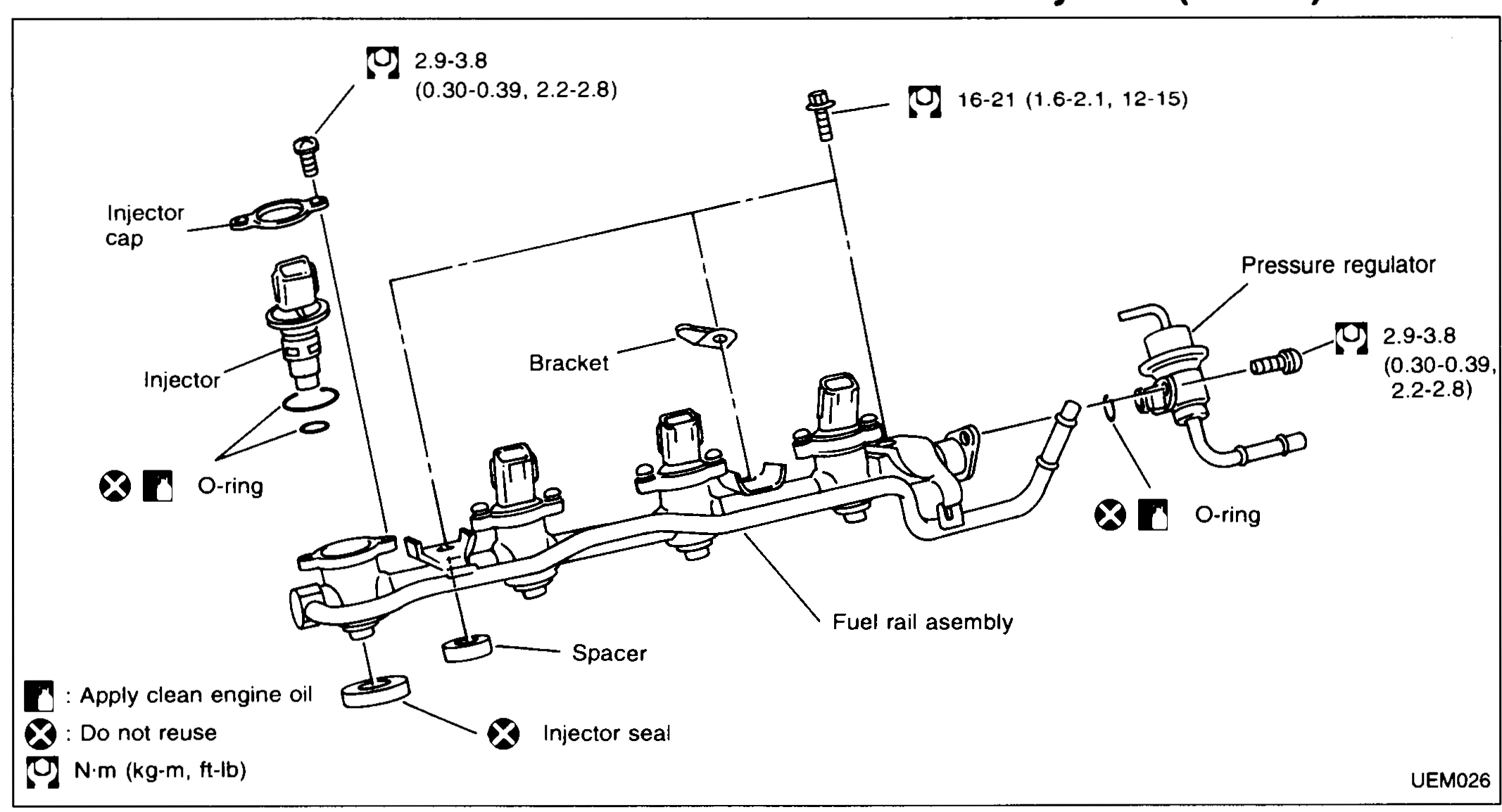
| Specification | Value |
|---|---|
| Injector cap / pressure regulator boltsTightening torque | 2.9 - 3.8N·m |
| Fuel rail bracket boltsTightening torque | 16 - 21N·m |
Injector cap / pressure regulator boltsTightening torque
2.9 - 3.8N·m
Fuel rail bracket boltsTightening torque
16 - 21N·m
NOTE
Legend: oil-can symbol = Apply clean engine oil; ⊗ = Do not reuse; torque-wrench symbol = N·m (kg-m, ft-lb).
FUEL RAIL
Removal
Fuel rail removal
- 1Release fuel pressure. Refer to FE section.
- 2Remove air cleaner assembly.
- 3Disconnect hoses and remove throttle body unit.
- 4Disconnect injector harness and remove fuel rail assembly.
 UEM027
Inspection
IMPORTANT
Check all components for wear, damage, etc. Refer to EF & EC section for injector electrical inspection. Replace all seals and O-rings.