
CYLINDER HEAD — Assembly and Installation (Supplement-V)
EM-5026prose procedureHead bolt is a stretch bolt — final pass is 255–265° of angle after 40 N·m preliminary torque. The cross-reference '(EM-00)' for OIL SEAL REPLACEMENT is preserved as printed (looks like a placeholder/source typo that should read EM-5017).
Assembly
Cylinder head — Assembly
- 1Install valve component parts.Always install new valve oil seals. Refer to "OIL SEAL REPLACEMENT", (EM-00).When installing valve, apply engine oil on the valve stem and lip of valve oil seal.Check whether the valve face is free from foreign matter.
- 2Install camshaft and brackets and tighten bracket nuts to the specified torque in two or three stages.Camshaft-bracket nuts torque: 20 N·m (2.0 kg-m, 14.8 ft-lb).Tighten bracket from center to outside.Apply sealant to brackets No. 1 and No. 3.Install new camshaft oil seal. Refer to "OIL SEAL REPLACEMENT", (EM-5017).
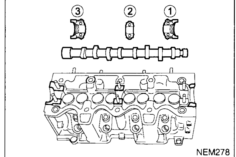 NEM278
 - 3Install camshaft hub and sprocket and tighten hub bolt to the specified torque using special service tool or a suitable tool.
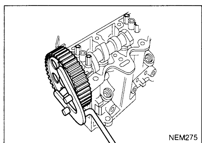 NEM275
 - 4Install camshaft locking pin SST KV109B0111.
- 5Install intake and exhaust manifold, EGR valve, vacuum pump and thermostat housing.
Installation
Cylinder head — Installation
- 1Install cylinder head gasket, with printing facing up.Confirm that the flywheel and injection pump locking pins are still fitted.When replacing or repairing cylinder block, piston, connecting rod and crankshaft, select piston referring to "DETERMINING THE PISTON TYPE", (EM-5041).
- 2Check cylinder head bolt length, and replace if limit is exceeded.Maximum length L: 197.5 mm (Hex head); 197.1 mm (TORX head).
 NEM279
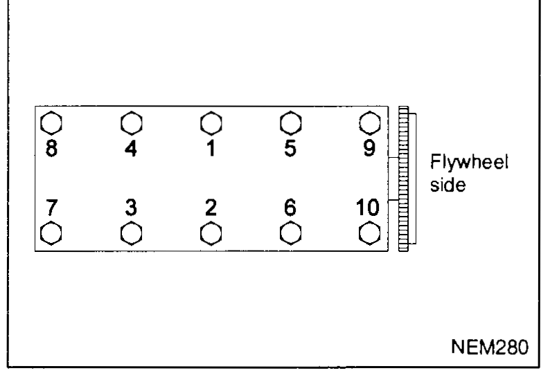
 - 3Install cylinder head and tighten cylinder head bolts according to the following sequence.
 NEM280
Tightening procedure
IMPORTANT
Apply MOLYKOTE G RAPID PLUS to threads and under-head seating face of each bolt.
Tightening procedure
- 1Tighten bolts in the numerical order shown in the figure and following the steps below using angle wrench SST KV10112100.
- aTighten all bolts to 40 N·m (4.1 kg-m, 29.5 ft-lb).
- bTurn all bolts 255° - 265°.
- 2Install timing belt. Refer to "TIMING BELT", (EM-5011).
| Specification | Value |
|---|---|
| Camshaft bracket nutTighten center → outside, 2–3 stages | ≈196N·m |
| Cylinder head bolt maximum length L — Hex headReplace if exceeded | 197.5mm |
| Cylinder head bolt maximum length L — TORX headReplace if exceeded | 197.1mm |
| Cylinder head bolt torque — step a (preliminary)All 10 bolts, in sequence | ≈392N·m |
| Cylinder head bolt — step b (angle pass)All 10 bolts, after preliminary torque | 255 - 265° |
Camshaft bracket nutTighten center → outside, 2–3 stages
196N·m
Cylinder head bolt maximum length L — Hex headReplace if exceeded
197.5mm
Cylinder head bolt maximum length L — TORX headReplace if exceeded
197.1mm
Cylinder head bolt torque — step a (preliminary)All 10 bolts, in sequence
392N·m
Cylinder head bolt — step b (angle pass)All 10 bolts, after preliminary torque
255 - 265°