
VALVE CLEARANCE — Checking and Adjusting (Supplement-V)
EM-5028prose procedureTwo-rotation method (rule of nine equivalent): measure half the valves with No.1 at TDC then rotate 360° and measure the rest. The shim-notch orientation tip is to make removal with the SST clearance-adjustment tool easier on the next page.
Checking
IMPORTANT
Check valve clearance while engine is cold and not running.
Valve clearance — Checking
- 1Remove rocker cover.
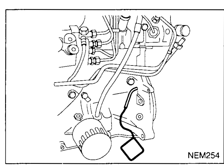
- 2Set No. 1 cylinder at TDC on its compression stroke.Install flywheel locking pin SST KV109B0112.Check that valve lifters on No. 1 cylinder are loose and valve lifters on No. 4 are tight. If not, turn crankshaft one revolution (360°) and align as above.
 NEM254
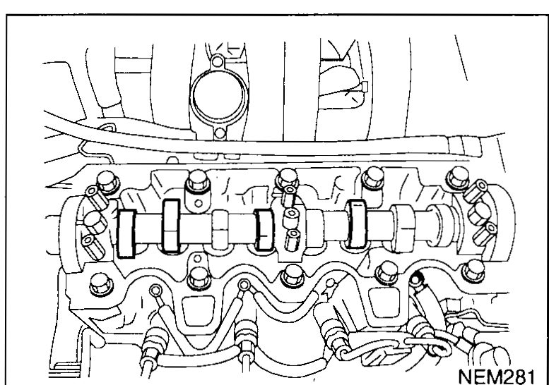
 - 3Check only those valves shown in the figure.Using a feeler gauge, measure clearance between valve lifter and camshaft.Record any valve clearance measurements which are out of specification. They will be used later to determine the required replacement adjusting shim.Valve clearance for checking (Cold) — Intake: 0.07 - 0.23 mm (0.003 - 0.009 in); Exhaust: 0.22 - 0.38 mm (0.009 - 0.015 in).
 NEM281
 - 4Turn crankshaft one revolution (360°) and install flywheel locking pin SST KV109B0112.
- 5Check those valves shown in the figure.Use the same procedure as mentioned in step 3.
 NEM282
 - 6If all valve clearances are within specification, install the rocker cover. Refer to "CYLINDER HEAD", (EM-5027).
Adjusting
IMPORTANT
Adjust valve clearance while engine is cold.
Valve clearance — Adjusting
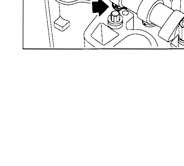
- 1Turn crankshaft, to position cam lobe on camshaft of valve that must be adjusted upward.Rotate notch toward injection nozzle (see figure) to simplify shim removal later.
 NEM284
| Specification | Value |
|---|---|
| Valve clearance for checking (Cold) — IntakeEngine cold, between valve lifter and camshaft base circle | 0.07 - 0.23 (0.003 - 0.009)mm (in) |
| Valve clearance for checking (Cold) — ExhaustEngine cold, between valve lifter and camshaft base circle | 0.22 - 0.38 (0.009 - 0.015)mm (in) |
Valve clearance for checking (Cold) — IntakeEngine cold, between valve lifter and camshaft base circle
0.07 - 0.23 (0.003 - 0.009)mm (in)
Valve clearance for checking (Cold) — ExhaustEngine cold, between valve lifter and camshaft base circle
0.22 - 0.38 (0.009 - 0.015)mm (in)