
CYLINDER HEAD — Disassembly and Inspection (Distortion) (Supplement-V)
EM-5021prose procedureTwo flatness numbers appear: the body text gives 0.05 mm (limit) and resurfacing limit 0.4 mm; the figure caption gives a warpage threshold of 0.1 mm (different criterion — likely the maximum allowable warpage before disassembly inspection vs. final flatness after resurfacing). Both are recorded.
Disassembly
Cylinder head — Disassembly
- 1Remove EGR valve, intake and exhaust manifold, vacuum pump and thermostat housing.
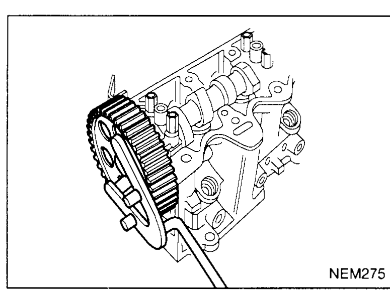
- 2Remove camshaft sprocket and hub using SST KV109B0070 or a suitable tool.
 NEM275
 - 3Remove camshaft brackets in order from outside to inside.Loosen camshaft bracket nuts in two or three stages.
- 4Remove camshaft and oil seal.
- 5Remove valve lifters.
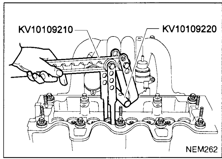
- 6Remove valve component parts using special service tool or a suitable tool.Keep each valve and its components together and mark them so they can be reassembled in their original positions.
 NEM262
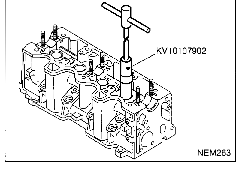
 - 7Remove valve oil seals using special service tool or a suitable tool.
 NEM263
Inspection
CYLINDER HEAD DISTORTION
Cylinder head distortion inspection
- 1Visually check for cracks and deformation.
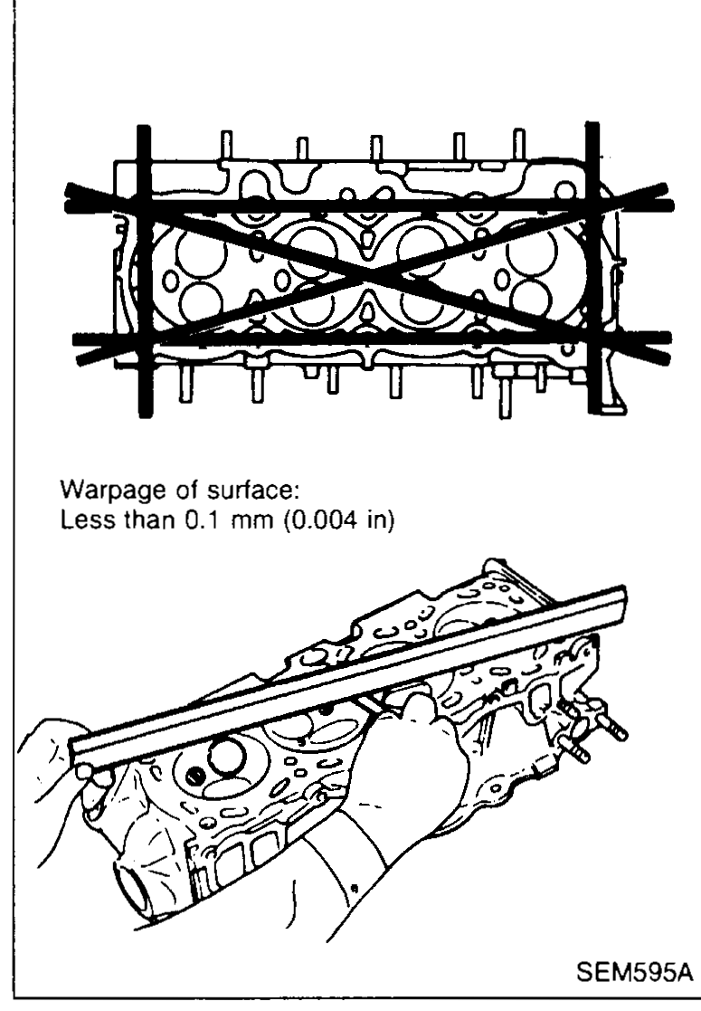
- 2Check cylinder head for distortion.Head surface flatness: Less than 0.05 mm (0.002 in).If beyond the specified limit, replace or resurface cylinder head.Resurfacing limit: 0.4 mm (0.016 in).After resurfacing cylinder head, check that camshaft rotates freely by hand. If resistance is felt, the cylinder head must be replaced.Nominal height of cylinder head: 136.3 - 136.5 mm (5.366 - 5.374 in).
 SEM595A
| Specification | Value |
|---|---|
| Head surface flatnessIf exceeded — resurface or replace | Less than 0.05 (0.002)mm (in) |
| Resurfacing limitMax material removed by resurfacing | 0.4 (0.016)mm (in) |
| Nominal height of cylinder headAfter resurfacing — check camshaft turns freely | 136.3 - 136.5 (5.366 - 5.374)mm (in) |
| Warpage of surface (figure note)Straightedge across head — see SEM595A | Less than 0.1 (0.004)mm (in) |
Head surface flatnessIf exceeded — resurface or replace
Less than 0.05 (0.002)mm (in)
Resurfacing limitMax material removed by resurfacing
0.4 (0.016)mm (in)
Nominal height of cylinder headAfter resurfacing — check camshaft turns freely
136.3 - 136.5 (5.366 - 5.374)mm (in)
Warpage of surface (figure note)Straightedge across head — see SEM595A
Less than 0.1 (0.004)mm (in)