
OUTER COMPONENT PARTS — Exhaust Manifold and Catalyser / Removal / Inspection / Assembly
EM-10prose procedureExhaust Manifold and Catalyser
Parts Diagram
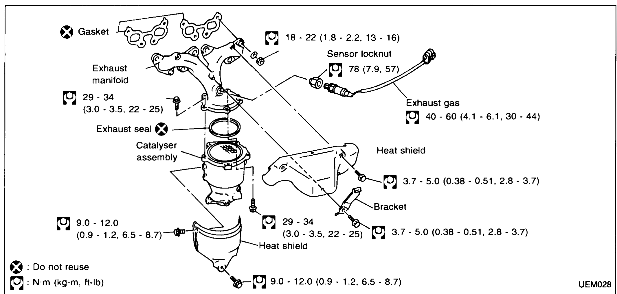
| Specification | Value |
|---|---|
| Exhaust manifold-to-head studs/nutsTightening torque | 29 - 34N·m |
| Catalyser bracket boltsTightening torque | 9.0 - 12.0N·m |
| Sensor locknutTightening torque | 78N·m |
| Heat-shield bracket boltTightening torque | 18 - 22N·m |
| Exhaust gas sensor (oxygen sensor)Tightening torque | 40 - 60N·m |
| Heat shield screwsTightening torque | 3.7 - 5.0N·m |
Exhaust manifold-to-head studs/nutsTightening torque
29 - 34N·m
Catalyser bracket boltsTightening torque
9.0 - 12.0N·m
Sensor locknutTightening torque
78N·m
Heat-shield bracket boltTightening torque
18 - 22N·m
Exhaust gas sensor (oxygen sensor)Tightening torque
40 - 60N·m
Heat shield screwsTightening torque
3.7 - 5.0N·m
NOTE
Legend: ⊗ = Do not reuse. Torque-wrench symbol indicates N·m (kg-m, ft-lb).
REMOVAL
Exhaust manifold & catalyser removal
- 1Remove heat shields.
- 2Disconnect exhaust front pipe.
- 3Remove catalyser and seal.
 UEM029
 - 4Remove exhaust gas sensor.
- 5Remove manifold.
INSPECTION
Exhaust manifold inspection
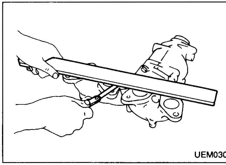
- 1Check all components for wear, damage, etc.Do not attempt to disassemble the catalyser honeycomb.
- 2Check flatness of manifold face using straightedge. Maximum variation: 0.3 mm (0.012 in).
 UEM030
| Specification | Value |
|---|---|
| Exhaust manifold flange flatness — Maximum variationLimit (straight-edge check) | 0.3 (0.012)mm (in) |
Exhaust manifold flange flatness — Maximum variationLimit (straight-edge check)
0.3 (0.012)mm (in)
Assembly
Exhaust manifold & catalyser assembly
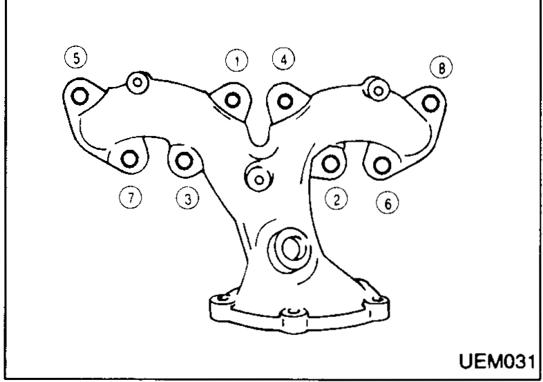
- 1Fit manifold. Tighten nuts as shown.
 UEM031
 - 2Fit exhaust gas sensor.
- 3Fit catalyser, using new seal.
- 4Fit exhaust pipe and heat shields.