
CYLINDER HEAD - Inspection (Cont'd) - Camshaft Journal OD / End Play / Sprocket Runout / Valve Guide Clearance
EM-31prose procedureInspection (Cont'd)
CAMSHAFT JOURNAL CLEARANCE (continued)
- 3Measure outer diameter of camshaft journal.Standard outer diameter (intake and exhaust): No. 1 journal 27.935 - 27.955 mm (1.0998 - 1.1006 in); No. 2 to No. 5 journals 23.435 - 23.455 mm (0.9226 - 0.9234 in)
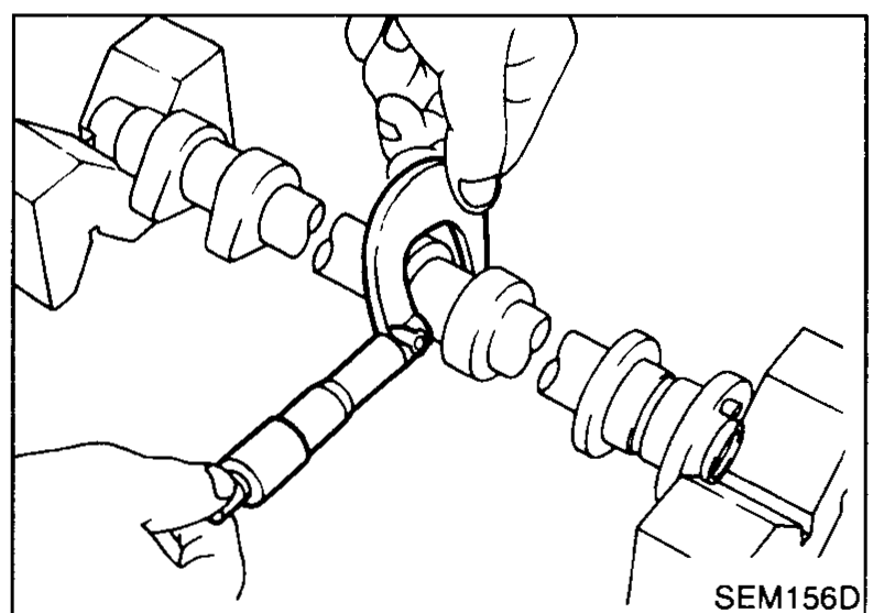 SEM156D
 - 4If clearance exceeds the limit, replace camshaft and/or cylinder head.Camshaft journal clearance: Standard 0.045 - 0.086 mm (0.0018 - 0.0034 in); Limit 0.15 mm (0.0059 in)
| Specification | Value |
|---|---|
| Camshaft journal standard outer diameter - No. 1 journalIntake and exhaust | 27.935 - 27.955mm (1.0998 - 1.1006 in) |
| Camshaft journal standard outer diameter - No. 2 to No. 5 journalsIntake and exhaust | 23.435 - 23.455mm (0.9226 - 0.9234 in) |
| Camshaft journal clearance - Standard | 0.045 - 0.086mm (0.0018 - 0.0034 in) |
| Camshaft journal clearance - Limit | 0.15mm (0.0059 in) |
Camshaft journal standard outer diameter - No. 1 journalIntake and exhaust
27.935 - 27.955mm (1.0998 - 1.1006 in)
Camshaft journal standard outer diameter - No. 2 to No. 5 journalsIntake and exhaust
23.435 - 23.455mm (0.9226 - 0.9234 in)
Camshaft journal clearance - Standard
0.045 - 0.086mm (0.0018 - 0.0034 in)
Camshaft journal clearance - Limit
0.15mm (0.0059 in)
CAMSHAFT END PLAY
- 1Install camshaft in cylinder head.
- 2Measure camshaft end play.Camshaft end play: Standard 0.070 - 0.143 mm (0.0028 - 0.0056 in); Limit 0.20 mm (0.0079 in)
 SEM157D
| Specification | Value |
|---|---|
| Camshaft end play - Standard | 0.070 - 0.143mm (0.0028 - 0.0056 in) |
| Camshaft end play - Limit | 0.20mm (0.0079 in) |
Camshaft end play - Standard
0.070 - 0.143mm (0.0028 - 0.0056 in)
Camshaft end play - Limit
0.20mm (0.0079 in)
CAMSHAFT SPROCKET RUNOUT
- 1Install sprocket on camshaft.
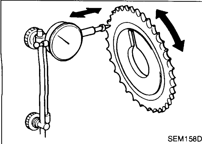
- 2Measure camshaft sprocket runout.Runout (Total indicator reading): Limit 0.15 mm (0.0059 in)
 SEM158D
 - 3If it exceeds the limit, replace camshaft sprocket.
| Specification | Value |
|---|---|
| Camshaft sprocket runout (Total indicator reading) - Limit | 0.15mm (0.0059 in) |
Camshaft sprocket runout (Total indicator reading) - Limit
0.15mm (0.0059 in)
VALVE GUIDE CLEARANCE
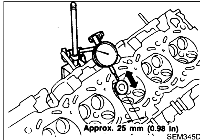
- 1Measure valve deflection in a parallel direction with rocker arm. (Valve and valve guide mostly wear in this direction.)Valve deflection limit (Dial gauge reading): Intake & Exhaust 0.2 mm (0.008 in)
 SEM345D
| Specification | Value |
|---|---|
| Valve deflection limit (Dial gauge reading) - Intake & Exhaust | 0.2mm (0.008 in) |
Valve deflection limit (Dial gauge reading) - Intake & Exhaust
0.2mm (0.008 in)