
CYLINDER BLOCK — Inspection (Cont'd); Crankshaft; Bearing Clearance (Supplement-V)
EM-5038prose procedurePiston diameter 'A' is given as a single value (76.939 mm). Piston-to-bore clearance 'B' is the resulting range (0.07-0.10 mm). NEM297 explicitly numbers main bearing No.1 at the flywheel side — same convention as the main-bearing-cap loosening order on EM-5036.
Inspection (Cont'd)
Piston-to-bore clearance (continued)
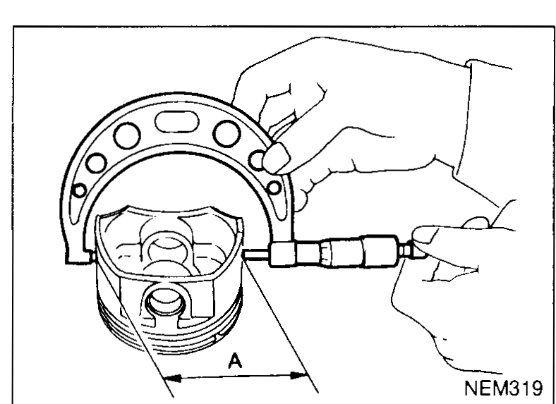
- 3Measure piston skirt diameter.Piston diameter "A": 76.939 mm (3.0291 in)
 NEM319
 - 4Check piston-to-bore clearance. If out of specification, replace piston and/or cylinder block.Piston-to-bore clearance "B": 0.07 - 0.10 mm (0.003 - 0.004 in)
CRANKSHAFT
Crankshaft inspection
- 1Check crankshaft main and pin journals for score, wear or cracks.
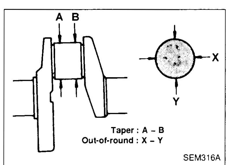
- 2With a micrometer, measure journals for taper and out-of-round.Out-of-round (X − Y): Less than 0.005 mm (0.0002 in)Taper (A − B): Less than 0.005 mm (0.0002 in)
 SEM316A
 - 3Measure crankshaft runout.Runout (Total indicator reading): Less than 0.05 mm (0.0020 in)
 SEM346D
BEARING CLEARANCE
Main bearing
Main bearing clearance
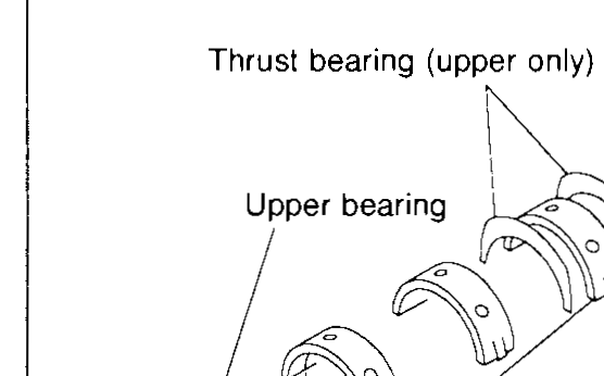
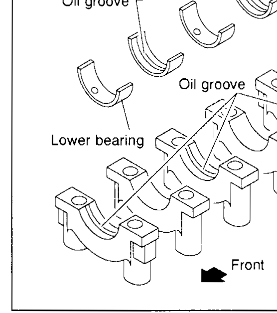
- 1Set main bearings in their proper positions on cylinder block and main bearing cap.Thrust bearing is fitted upper only.Upper bearings have an oil groove; lower bearings do not.No.1 bearing is at the flywheel side.
 NEM297