
OUTER COMPONENT PARTS — Intake Manifold & Fuel System (Cont'd)
EM-8parts diagramIntake Manifold & Fuel System (Cont'd)
Parts DiagramFig. fig1
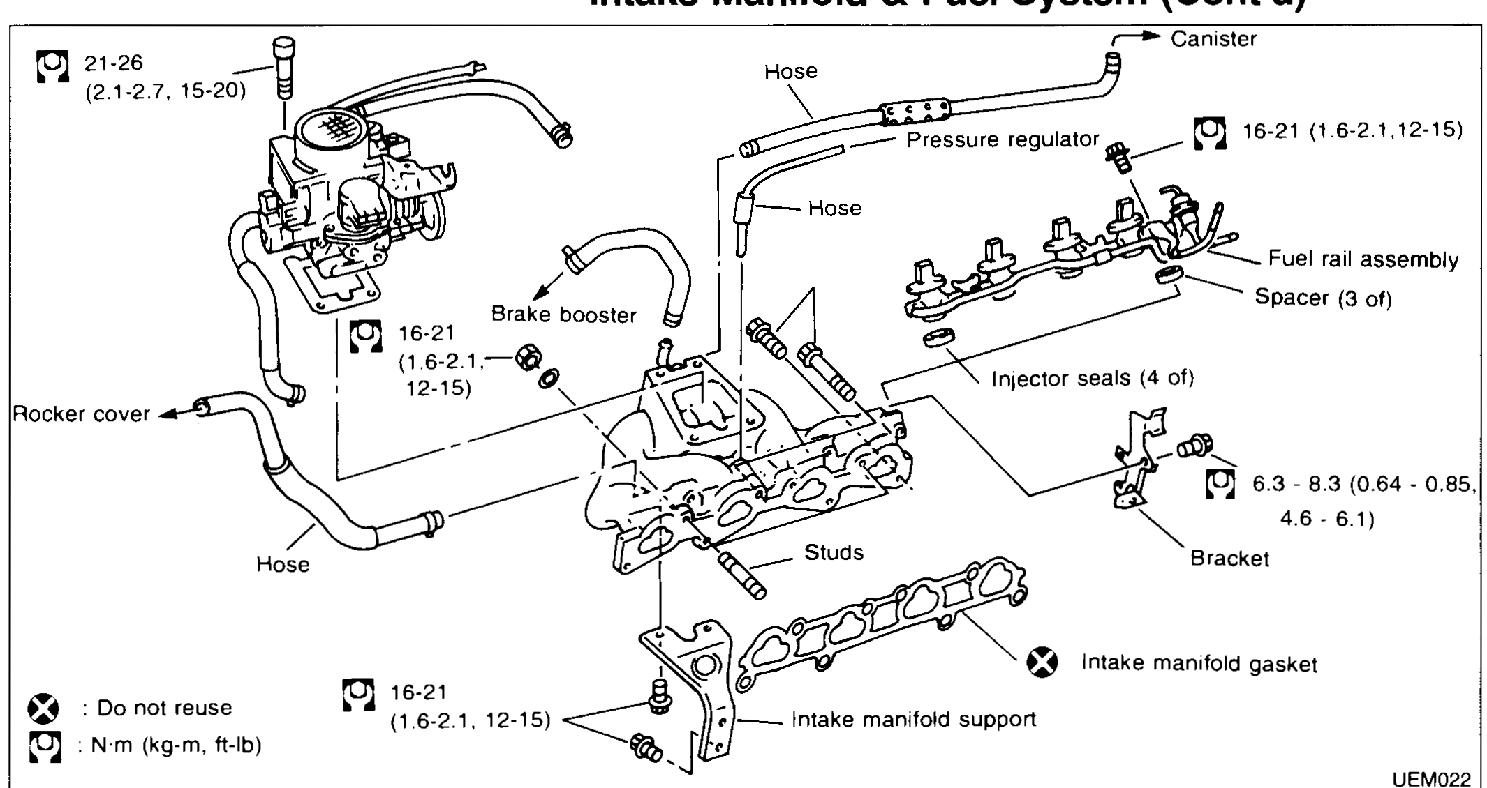
| Specification | Value |
|---|---|
| Throttle body / large intake fastenerTightening torque | 21 - 26N·m |
| Intake manifold bolts / nuts (multiple positions)Tightening torque | 16 - 21N·m |
| Fuel rail / bracket fastenersTightening torque | 6.3 - 8.3N·m |
Throttle body / large intake fastenerTightening torque
21 - 26N·m
Intake manifold bolts / nuts (multiple positions)Tightening torque
16 - 21N·m
Fuel rail / bracket fastenersTightening torque
6.3 - 8.3N·m
INTAKE MANIFOLD
Removal
Intake manifold removal
- 1Release fuel pressure. Refer to FE section.
- 2Remove air cleaner and disconnect hoses.
- 3Remove throttle body assembly.
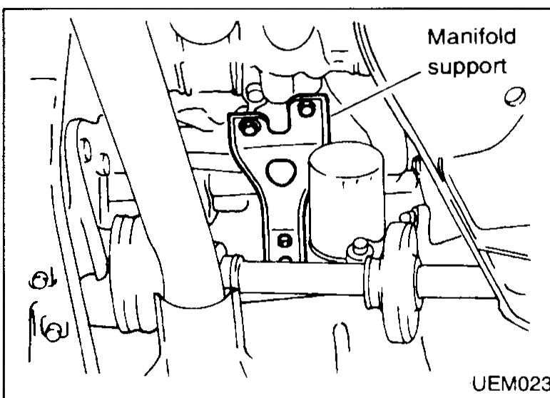
- 4Remove manifold support.
 UEM023
 - 5Remove manifold.
Inspection
Intake manifold inspection
- 1Check manifold with straight edge. Variation limit: 0.1 mm (0.0039 in)
 UEM024
Reassembly
Intake manifold reassembly
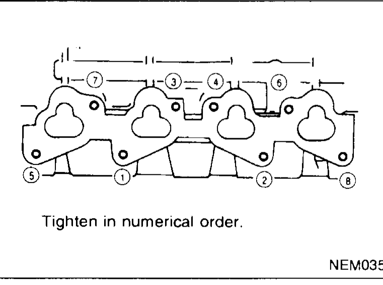
- 1Fit the manifold. Torque bolts/nuts in order shown.
 NEM035
 - 2Refit manifold support and throttle body.
- 3Reconnect hoses & fit air cleaner.
IMPORTANT
Ensure all nuts/bolts are torqued securely.
Check for fuel and air leaks.