
CYLINDER BLOCK — Determining the Piston Type (Cont'd) (Supplement-V)
EM-5042prose procedureSelection table has overlapping reading ranges between the A/B/C bands (2.50-2.40, 2.43-2.33, 2.36-2.26 — they overlap at 2.36-2.40 and 2.33-2.43); preserved verbatim from source. Out-of-range readings ('Below 2.26' and 'Above 2.5') call for 'Check dimensions of all elements'. The Final Protrusion Dimension column is a single merged cell in the source (1.09 ± 0.05 mm applies to all rows); replicated per-row so the keyed table renders consistently.
Inspection (Cont'd)
Determining the piston type (continued)
- 5Install the connecting rod bearing cap and tighten to the specified torque.
- 6Install the dial indicator on the dial support.
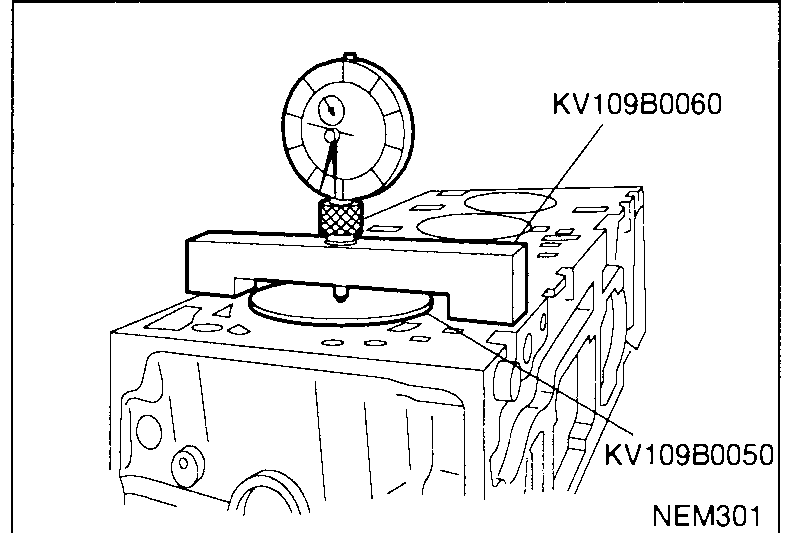 NEM301
 - 7Place the indicator/support above the center of calibration piston.
- 8Turn the crankshaft to TDC, and zero out the dial indicator.
- 9Move the indicator/support onto the deck.
 NEM302
 - 10Take a precise reading of the difference in level between calibration piston and the deck.
- 11Follow the same procedure for the other cylinders, using the corresponding connecting rods.
- 12Select piston height types according to the following table.
Piston height type selection — dial indicator reading to piston reference
Below 2.26 (0.089)
Piston ReferenceCheck dimensions of all elements
Final Protrusion Dimension1.09 ± 0.05 (0.043 ± 0.002)
2.50 - 2.40 (0.098 - 0.094)
Piston ReferenceA
Final Protrusion Dimension1.09 ± 0.05 (0.043 ± 0.002)
2.43 - 2.33 (0.096 - 0.092)
Piston ReferenceB
Final Protrusion Dimension1.09 ± 0.05 (0.043 ± 0.002)
2.36 - 2.26 (0.093 - 0.089)
Piston ReferenceC
Final Protrusion Dimension1.09 ± 0.05 (0.043 ± 0.002)
Above 2.5 (0.098)
Piston ReferenceCheck dimensions of all elements
Final Protrusion Dimension1.09 ± 0.05 (0.043 ± 0.002)