
TIMING CHAIN - Installation (Cont'd)
EM-21prose procedureUnverifiedInstallation (Cont'd)
Installation (continued)
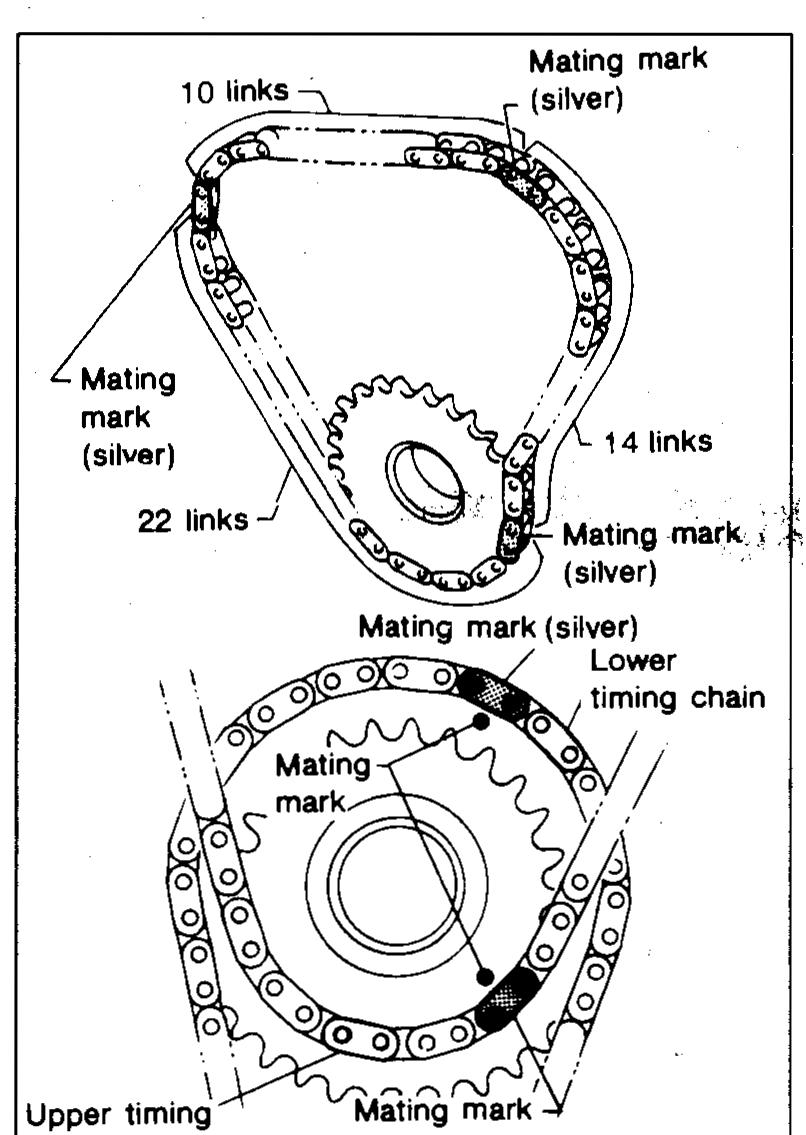
- 11Set idler sprocket by aligning the mating mark on the larger sprocket with the silver mating mark on the lower timing chain.22 links between silver marks at lower chain (idler small sprocket)
 UEM109
 - 12Install upper timing chain and set it by aligning the mating mark on the smaller sprocket with the silver mating marks on the upper timing chain.Make sure sprocket's mating mark faces engine front.10 links between silver marks on upper-chain large idler segment14 links on small idler sprocket
- 13Install idler sprocket shaft from the rear side.Ensure that the shaft is located correctly, as shown.
 UEM054
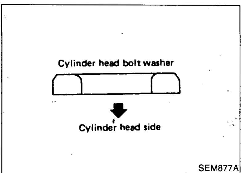
 - 14Install cylinder head with new gasket.Be sure to install washers between bolts and cylinder head.Do not rotate crankshaft and camshaft separately, or valves will strike piston heads.
 SEM877A
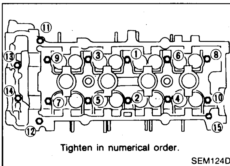
Tightening procedure (bolts 1-10)
- 1(a) Tighten bolts to 39 N·m (4.0 kg-m, 29 ft-lb).
 SEM124D
 - 2(b) Tighten bolts to 78 N·m (8.0 kg-m, 58 ft-lb).
- 3(c) Loosen bolts completely.
- 4(d) Tighten bolts to [?] N·m (3.6 kg-m, 26 ft-lb).N·m value partially obscured; kg-m and ft-lb readable as 3.6 / 26
- 5(e) Turn bolts 60 degrees clockwise.
- 6(f) Tighten bolts (11) - (6) to 6.3 to 8.3 N·m (0.64 to 0.85 kg-m, 4.6 to 6.1 ft-lb).
| Specification | Value |
|---|---|
| Cylinder head bolts - step (a) | 39N·m (4.0 kg-m, 29 ft-lb) |
| Cylinder head bolts - step (b) | 78N·m (8.0 kg-m, 58 ft-lb) |
| Cylinder head bolts - step (c) | Loosen completely |
| Cylinder head bolts - step (d)N·m digit not legible | ≈35N·m |
| Cylinder head bolts - step (e) | Turn 60° clockwisedegrees |
| Cylinder head bolts (11)-(6) - step (f) | 6.3 - 8.3N·m |
| Upper timing chain - links between silver marks (large segment) | 10links |
| Upper timing chain - links to small idler sprocket | 14links |
| Lower timing chain - links between silver marks | 22links |
Cylinder head bolts - step (a)
39N·m (4.0 kg-m, 29 ft-lb)
Cylinder head bolts - step (b)
78N·m (8.0 kg-m, 58 ft-lb)
Cylinder head bolts - step (c)
Loosen completely
Cylinder head bolts - step (d)N·m digit not legible
35N·m
Cylinder head bolts - step (e)
Turn 60° clockwisedegrees
Cylinder head bolts (11)-(6) - step (f)
6.3 - 8.3N·m
Upper timing chain - links between silver marks (large segment)
10links
Upper timing chain - links to small idler sprocket
14links
Lower timing chain - links between silver marks
22links