
ENGINE REMOVAL — Removal (Cont'd) Steps 29-44 / Installation Steps 1-2
EM-41prose procedureStep "Attach engine slinger brackets to engine" appears between steps 39 and 40 in the printed prose as an unnumbered bullet — captured here as "39b" to preserve sequence. Step numbering otherwise verbatim.
Removal (Cont'd)
Engine removal (continued steps 29-44)
- 29Remove engine harness from harness saddle on engine mounting.
- 30Disconnect two engine temperature sensors.
- 31Remove main earth lead from body.
- 32On power steering equipped models, slacken water pump drive belt. Refer to section MA. Remove alternator. Loosen and remove power steering pump fixing bolts. Tie power steering pump onto vehicle body.
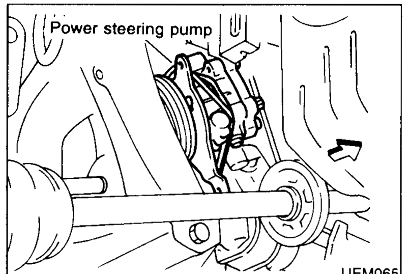 UEM065
 - 33Disconnect fuel lines.
- 34Disconnect kickdown cable (NCVT).
- 35Disconnect speedometer cable.
- 36Disconnect throttle cable.
- 37Disconnect carbon canister hoses.
- 38Disconnect brake vacuum hose from brake servo.
- 39On air conditioning equipped models, slacken alternator drive belt. Refer to section MA. Remove alternator. Loosen and remove air conditioning compressor fixing bolts. Tie air conditioning compressor onto vehicle body.
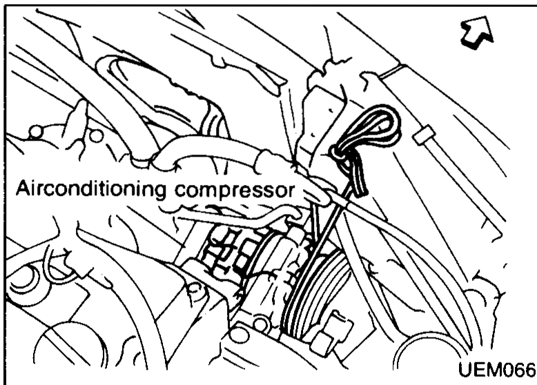 UEM066
 - 39bAttach engine slinger brackets to engine. Engine slinger brackets and engine slinger bracket bolts are described in PARTS CATALOG.Bracket part numbers and bolts are in PARTS CATALOG, not this manual.
- 40Remove 4 centermember mounting bolts from vehicle body.
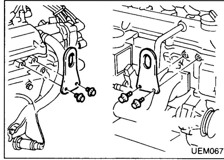 UEM067
 - 41Remove centermember from engine.
- 42Attach slingers to engine slinger brackets and use crane to release load from both top engine mountings.
 UEM068
 - 43Disconnect or remove engine mountings.
- 44Lower engine onto transmission jack or floor.
Installation
Engine installation
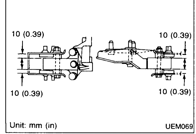
- 1Install top engine mounting brackets and fixing bolts. Insulator must protrude 10 mm (0.39 in) on each side of bracket.Ensure that insulators are positioned on brackets correctly.
 UEM069
 - 2Carefully move engine onto engine mounting insulators.
| Specification | Value |
|---|---|
| Engine mounting insulator protrusion (each side)Both sides of bracket | 10 (0.39)mm (in) |
Engine mounting insulator protrusion (each side)Both sides of bracket
10 (0.39)mm (in)
See also
MA — Drive belt adjustment · PARTS CATALOG — Engine slinger brackets