
CYLINDER BLOCK — Inspection (Cont'd) / Crankshaft
EM-49prose procedureSource page misprints "instructions" as "intructions" in step 8; transcribed verbatim as printed.
Inspection (Cont'd)
Piston-to-bore clearance (continued)
- 3Measure piston skirt diameter. Piston diameter "A": 70.980 - 71.010 mm (2.7945 - 2.7957 in). Measuring point "a" (Distance from the bottom): 9.5 mm (0.374 in).
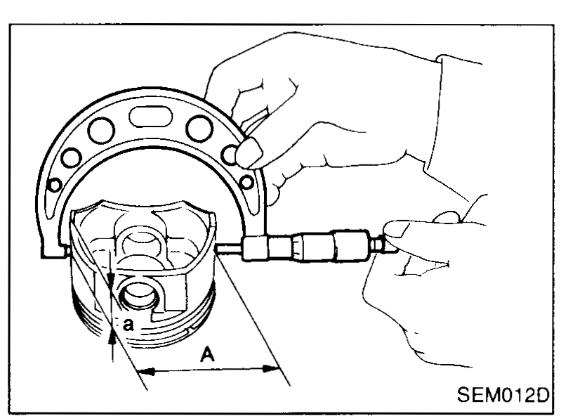 SEM012D
 - 4Check that piston-to-bore clearance is within specification. Piston-to-bore clearance "B": 0.010 - 0.030 mm (0.0004 - 0.0012 in).
- 5Determine piston oversize according to amount of cylinder wear.Oversize pistons are available for service. Refer to S.D.S.
- 6Cylinder bore size is determined by adding piston-to-bore clearance to piston diameter "A". Rebored size calculation: D = A + B − C, where, D: Bored diameter, A: Piston diameter as measured, B: Piston-to-bore clearance, C: Honing allowance 0.02 mm (0.0008 in).
- 7Install main bearing caps, and tighten to the specified torque to prevent distortion of cylinder bores in final assembly.
- 8Cut cylinder bores.When any cylinder needs boring, all other cylinders must also be bored.Ensure that boring machines intructions are closely followed.
- 9Hone cylinders to obtain specified piston-to-bore clearance.
- 10Measure finished cylinder bore for out-of-round and taper.Measurement should be done after cylinder bore cools down.
| Specification | Value |
|---|---|
| Piston diameter "A" — StandardMeasuring point 9.5 mm from bottom | 70.980 - 71.010 (2.7945 - 2.7957)mm (in) |
| Piston measuring point "a" (distance from bottom)Reference dimension | 9.5 (0.374)mm (in) |
| Piston-to-bore clearance "B"Standard | 0.010 - 0.030 (0.0004 - 0.0012)mm (in) |
| Honing allowance "C"Used in D = A + B − C | 0.02 (0.0008)mm (in) |
Piston diameter "A" — StandardMeasuring point 9.5 mm from bottom
70.980 - 71.010 (2.7945 - 2.7957)mm (in)
Piston measuring point "a" (distance from bottom)Reference dimension
9.5 (0.374)mm (in)
Piston-to-bore clearance "B"Standard
0.010 - 0.030 (0.0004 - 0.0012)mm (in)
Honing allowance "C"Used in D = A + B − C
0.02 (0.0008)mm (in)
CRANKSHAFT
Crankshaft inspection
- 1Check crankshaft main and pin journals for score, wear or cracks.
- 2With a micrometer, measure journals for taper and out-of-round. Out-of-round (X − Y): Less than 0.005 mm (0.0002 in). Taper (A − B): Less than 0.002 mm (0.0001 in).
 SEM316A
| Specification | Value |
|---|---|
| Crankshaft journal out-of-round (X − Y)Limit | Less than 0.005 (0.0002)mm (in) |
| Crankshaft journal taper (A − B)Limit | Less than 0.002 (0.0001)mm (in) |
Crankshaft journal out-of-round (X − Y)Limit
Less than 0.005 (0.0002)mm (in)
Crankshaft journal taper (A − B)Limit
Less than 0.002 (0.0001)mm (in)
See also
S.D.S.