
CYLINDER BLOCK — Assembly (Cont'd) / Piston Ring Gap Orientation / Crankshaft Installation
EM-54prose procedureAssembly (Cont'd)
NOTE
Set piston-ring end gaps as shown: top ring at upper right, oil-ring upper rail at upper right, oil-ring lower rail at lower right, 2nd ring at lower left, oil-ring expander at upper left; "Front" arrow points left.
CRANKSHAFT
Crankshaft installation
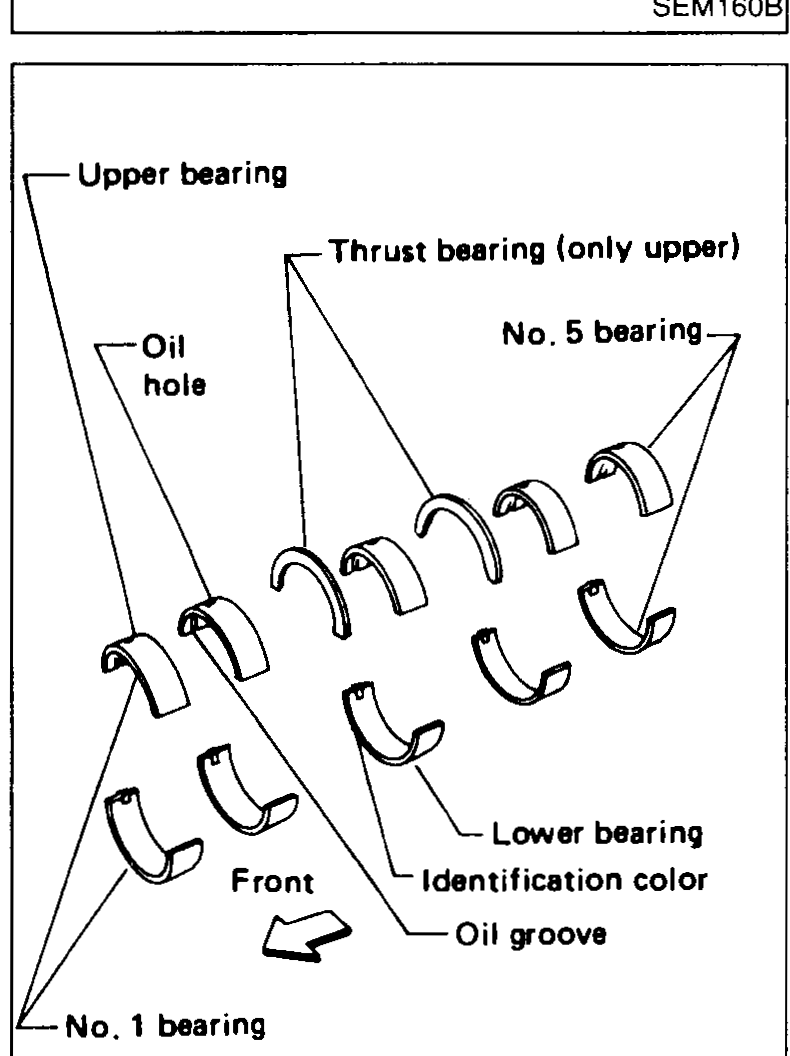
- 1Set main bearings in their proper positions on cylinder block and main bearing cap.Confirm that correct main bearings are used. Refer to "Inspection".
 SEM195C
 - 2Install crankshaft and main bearing beam and tighten bolts as follows.Prior to tightening bearing cap bolts, place bearing cap in its proper position by shifting crankshaft in the axial direction.After securing bearing cap bolts, make sure crankshaft turns smoothly by hand.
- Tighten main bearing beam bolts to 25 to 30 N·m (2.5 to 3.1 kg-m, 18 - 22 ft-lb) in order shown.
 NEM064
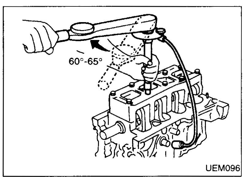
 - Turn bolts to 60° to 65° degrees clockwise with an angle wrench in order shown.
 UEM096
| Specification | Value |
|---|---|
| Main bearing beam bolts — Step 1Initial tightening, in order shown | 25 - 30N·m |
| Main bearing beam bolts — Step 2 angleAngle-torque with angle wrench | 60° - 65°degrees clockwise |
Main bearing beam bolts — Step 1Initial tightening, in order shown
25 - 30N·m
Main bearing beam bolts — Step 2 angleAngle-torque with angle wrench
60° - 65°degrees clockwise
See also
Inspection