
CYLINDER HEAD — Inspection (Cont'd) — Valve Guide & Valve Seats (Supplement-V)
EM-5022prose procedureInspection (Cont'd)
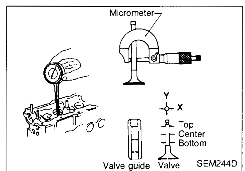
Valve guide clearance
- 1Measure valve stem diameter and valve guide inner diameter as illustrated.Standard clearance: 0.025 - 0.052 mm (0.0010 - 0.0020 in)
 SEM244D
Valve guide replacement
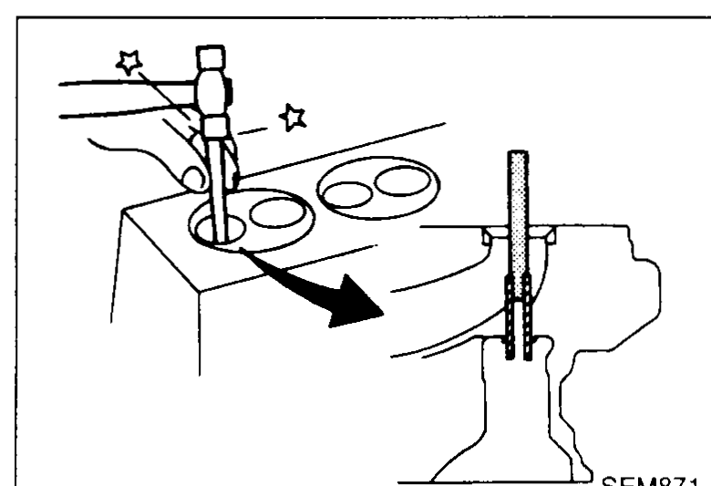
- 1Heat cylinder head in oil to 150 to 160°C (302 to 320°F).
- 2Drive out valve guide using a press or hammer and a suitable tool.
 SEM871
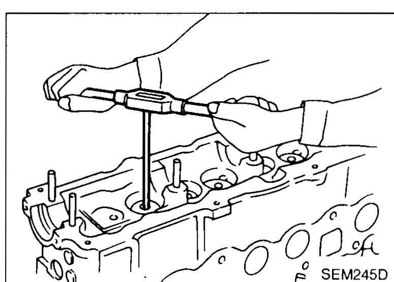
 - 3Ream cylinder head valve guide bore.Reaming bore (service part): 13.495 - 13.527 mm (0.5313 - 0.5326 in)
 SEM245D
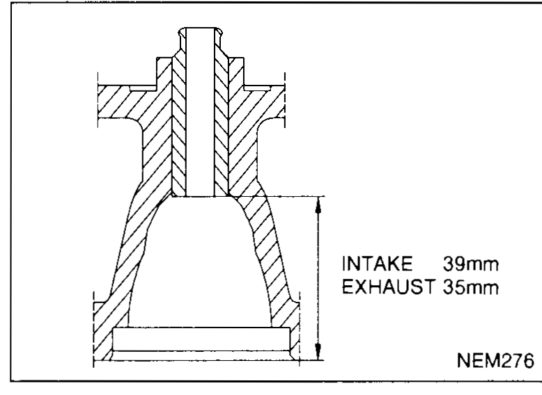
 - 4Heat cylinder head to 150 to 160°C (302 to 320°F) and press service valve guide onto cylinder head.Installed guide projection — INTAKE: 39 mm; EXHAUST: 35 mm (per figure NEM276)
 NEM276
VALVE SEATS
Valve seats inspection
- 1Check valve and valve seat for contact. Coat the valve face with prussian red lead. If contact is wrong, correct valve seat. If the valve red lead appears 360° around face, the valve stem and face are concentric. If not, repair or replace valve.
 SEM722BA
 - 2Check valve seats for pitting at contact surface. Resurface or replace if excessively worn. Correct valve seat surface.When repairing valve seat, check valve and valve guide for wear beforehand. If worn, replace them. Then correct valve seat.
| Specification | Value |
|---|---|
| Valve stem to valve guide standard clearanceTop / Center / Bottom measurement positions | 0.025 - 0.052 (0.0010 - 0.0020)mm (in) |
| Reaming bore (service part)After driving out old guide | 13.495 - 13.527 (0.5313 - 0.5326)mm (in) |
| Cylinder-head heating range for guide R&ROil bath | 150 - 160 (302 - 320)°C (°F) |
| Installed valve guide projection — IntakePer figure NEM276 | 39mm |
| Installed valve guide projection — ExhaustPer figure NEM276 | 35mm |
Valve stem to valve guide standard clearanceTop / Center / Bottom measurement positions
0.025 - 0.052 (0.0010 - 0.0020)mm (in)
Reaming bore (service part)After driving out old guide
13.495 - 13.527 (0.5313 - 0.5326)mm (in)
Cylinder-head heating range for guide R&ROil bath
150 - 160 (302 - 320)°C (°F)
Installed valve guide projection — IntakePer figure NEM276
39mm
Installed valve guide projection — ExhaustPer figure NEM276
35mm