
DTC P0710, P0711 CVT FLUID TEMPERATURE SENSOR CIRCUIT - Diagnostic Procedure (Cont'd)
AT-7061flowchartDiagnostic Procedure (Cont'd)
3. CHECK INPUT SIGNAL OF CVT FLUID TEMPERATURE SENSOR (Without CONSULT-II)
- 1Without CONSULT-II: Start engine.
- 2Check voltage between TCM terminal 28 and ground while warming up CVT. Voltage: Cold [20 deg C (68 deg F)] -> Hot [80 deg C (176 deg F)]: Approximately 2.4V -> 0.8V.
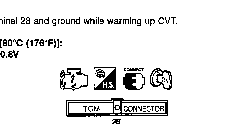 SAT420JA
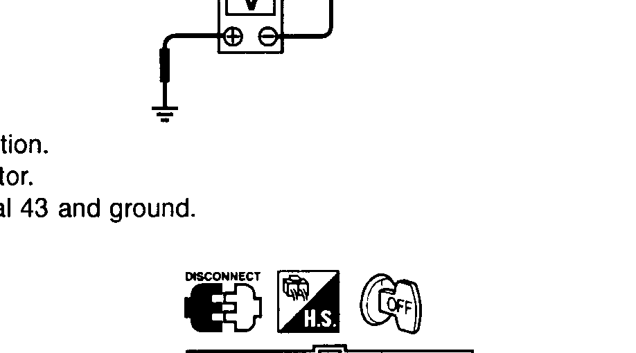
 - 3Turn ignition switch to "OFF" position.
- 4Disconnect TCM harness connector.
- 5Check continuity between terminal 43 and ground. Continuity should exist.
 SAT421J
NOTE
If OK, check harness for short to ground and short to power.
1
OK or NG
NG
Check the following item: Harness for short to ground or short to power or open between TCM, ECM and terminal cord assembly (Main harness); Ground circuit for ECM (Refer to EC section "TROUBLE DIAGNOSIS FOR POWER SUPPLY")
Check the following item: Harness for short to ground or short to power or open between TCM, ECM and terminal cord assembly (Main harness); Ground circuit for ECM (Refer to EC section "TROUBLE DIAGNOSIS FOR POWER SUPPLY")
OK
2
GO TO 4.
4. CHECK DTC
NOTE
Perform Diagnostic Trouble Code (DTC) confirmation procedure, AT-7058.
1
OK or NG
NG
1. Perform TCM input/output signal inspection. 2. If NG, recheck TCM pin terminals for damage or loose connection with harness connector.
OK
2
INSPECTION END