
DTC P0705 PARK/NEUTRAL POSITION (PNP) SWITCH - Diagnostic Procedure
AT-7054flowchartDiagnostic Procedure
1. CHECK PNP SWITCH CIRCUIT (With CONSULT-II)
- 1With CONSULT-II: Turn ignition switch to "ON" position. (Do not start engine.)
- 2Select "TCM INPUT SIGNALS" in "DATA MONITOR" mode for "CVT" with CONSULT-II.
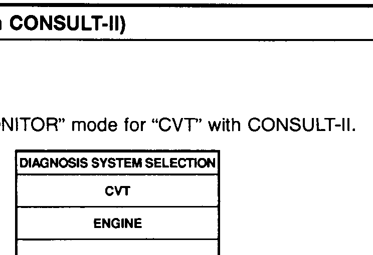 SAT651J
 - 3Read out "P/N", "R", "D" and "L" position switches moving selector lever to each position. Check the signal of the selector lever position is indicated properly.
1
OK or NG
NG
Check the following items: PNP switch (Refer to "Component Inspection", AT-7056); Harness for short or open between ignition switch and PNP switch (Main harness); Harness for short or open between PNP switch and TCM (Main harness); Ignition switch and fuse (Refer to EL section "POWER SUPPLY ROUTING"); Diode (P, N positions)
Check the following items: PNP switch (Refer to "Component Inspection", AT-7056); Harness for short or open between ignition switch and PNP switch (Main harness); Harness for short or open between PNP switch and TCM (Main harness); Ignition switch and fuse (Refer to EL section "POWER SUPPLY ROUTING"); Diode (P, N positions)
OK
2
GO TO 3.