
DTC P0705 PARK/NEUTRAL POSITION (PNP) SWITCH - Diagnostic Procedure (Cont'd)
AT-7055flowchartDiagnostic Procedure (Cont'd)
2. CHECK PNP SWITCH CIRCUIT (Without CONSULT-II)
- 1Without CONSULT-II: Turn ignition switch to "ON" position. (Do not start engine.)
- 2Check voltage between TCM terminals 32, 41, 47, 33, 48 and ground while moving selector lever through each position. Voltage: B: Battery voltage; 0: 0V.
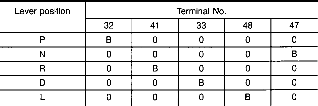 SAT197K
P
Terminal 32B
Terminal 410
Terminal 330
Terminal 480
Terminal 470
N
Terminal 320
Terminal 410
Terminal 330
Terminal 480
Terminal 47B
R
Terminal 320
Terminal 41B
Terminal 330
Terminal 480
Terminal 470
D
Terminal 320
Terminal 410
Terminal 33B
Terminal 480
Terminal 470
L
Terminal 320
Terminal 410
Terminal 330
Terminal 48B
Terminal 470
1
OK or NG
NG
Check the following items: PNP switch (Refer to "Component Inspection", AT-7056); Harness for short or open between ignition switch and PNP switch (Main harness); Harness for short or open between PNP switch and TCM (Main harness); Ignition switch and fuse (Refer to EL section "POWER SUPPLY ROUTING"); Diode (P, N positions)
Check the following items: PNP switch (Refer to "Component Inspection", AT-7056); Harness for short or open between ignition switch and PNP switch (Main harness); Harness for short or open between PNP switch and TCM (Main harness); Ignition switch and fuse (Refer to EL section "POWER SUPPLY ROUTING"); Diode (P, N positions)
OK
2
GO TO 3.
3. CHECK DTC
NOTE
Perform Diagnostic Trouble Code (DTC) confirmation procedure, AT-7052.
1
OK or NG
NG
1. Perform TCM input/output signal inspection. 2. If NG, recheck TCM pin terminals for damage or loose connection with harness connector.
OK
2
INSPECTION END