
REMOVAL AND INSTALLATION (MA5L)
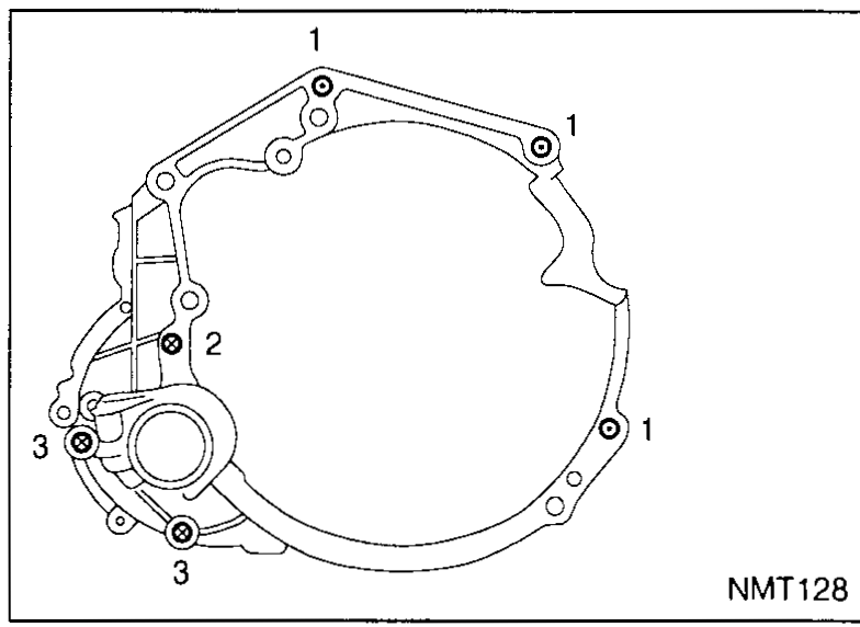
MT-5006prose procedureSupplement-V REMOVAL AND INSTALLATION for the MA5L transaxle. Bolt-position diagram (NMT128) identifies three positions; tightening torques given in N·m / kg-m / ft-lb.
Removal
Transaxle removal
- 1Remove battery and battery tray.
- 2Remove air cleaner.
- 3Disconnect clutch control cable from transaxle.
- 4Disconnect speedometer connector from transaxle.
- 5Disconnect reverse switch connector and ground harness.
- 6Remove starter motor from transaxle. Refer to section EL.
- 7Remove shift linkages from transaxle.
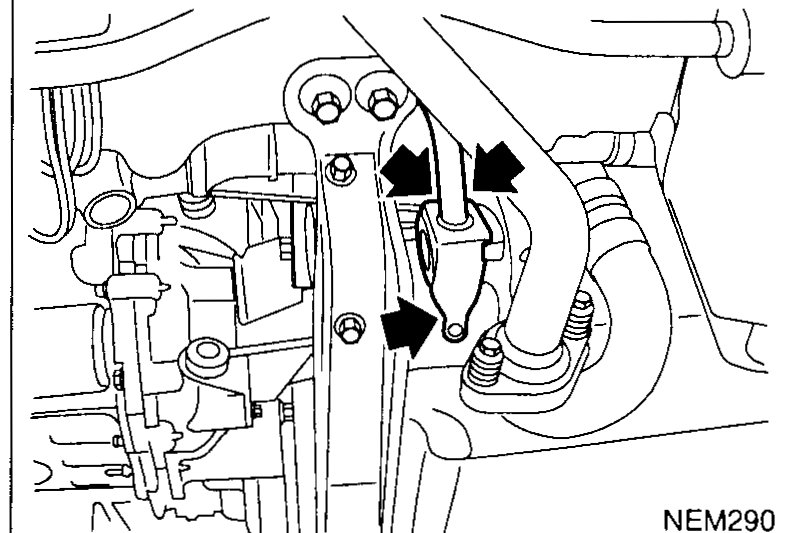 NEM290
 - 8Drain gear oil from transaxle.
- 9Remove exhaust front tube.
- 10Draw out drive shafts from transaxle — Refer to section FA.
- 11Support engine by placing a jack under oil pan.
 UMT015
 - 12Remove rear and LH mounts.
- 13Raise jack for access to lower housing bolts. Remove bolts. Lower jack.
- 14Remove bolts securing transaxle.
- 15Lower transaxle while supporting it with a jack.
Installation
NOTE
Tighten bolts securing transaxle.
1
Tightening torque N·m (kg-m, ft-lb)32 - 38 (3.3 - 3.9, 23.6 - 28.0)
2
Tightening torque N·m (kg-m, ft-lb)64 - 73 (6.5 - 7.4, 47.2 - 53.8)
3
Tightening torque N·m (kg-m, ft-lb)74 - 83 (7.5 - 8.5, 54.6 - 61.2)
NOTE
Reinstall any part removed.