
REPAIR FOR COMPONENT PARTS — Input Shaft and Gears (Cont'd) (RS5F30A & RS5F31V)
MT-43prose procedurePage applies to RS5F30A and RS5F31V transaxle variants. Steps 2-8 continue the assembly that began on MT-42; the bullet on this page ("Be careful not to hook ...") is a continuation of step 1's warning shown with figure TM131A.
Input Shaft and Gears (Cont'd)
Input shaft assembly (continued)
- 1-warningSpread-spring installation note (continued from MT-42 step 1).Be careful not to hook front and rear ends of spread spring to the same insert.
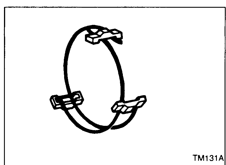 TM131A
 - 2Install bearing retainer.
 SMT731
 - 3Press on input shaft front bearing.
- 4Install input gear spacer.
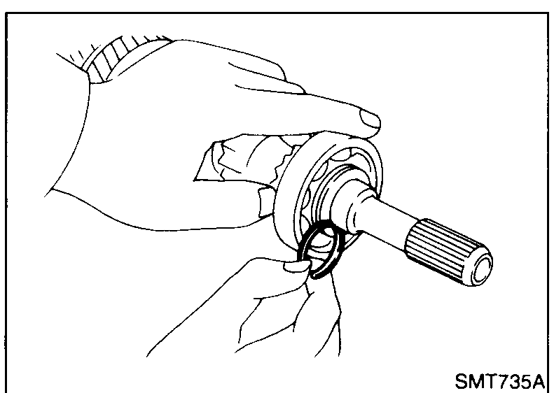
- 5Select proper snap ring of input shaft front bearing to minimize clearance of groove in input shaft and then install it.Allowable clearance of groove: 0 - 0.1 mm (0 - 0.004 in)Snap ring of input shaft front bearing: Refer to S.D.S.
 SMT735A
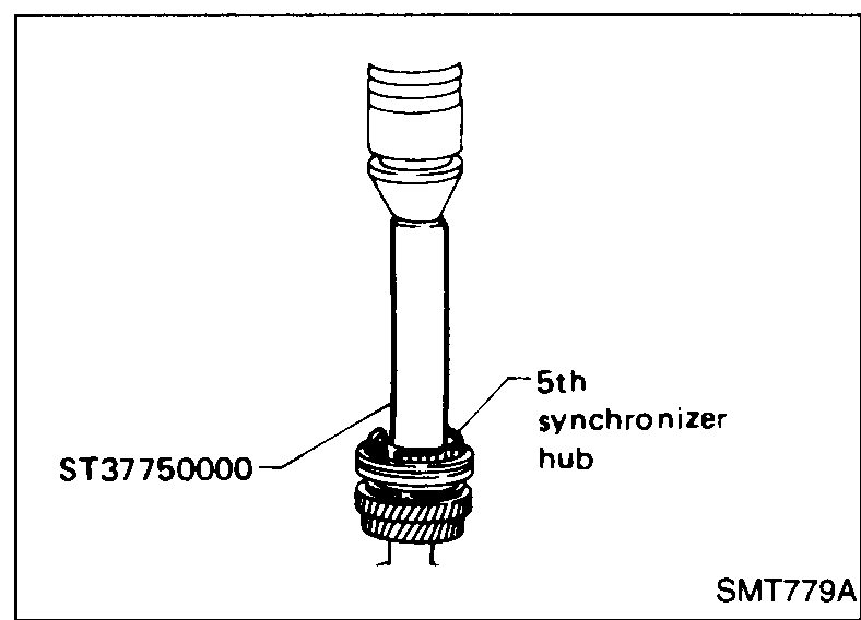
 - 6Install 5th gear needle bearing, 5th input gear, 5th synchronizer and 5th stopper.
 SMT779A
 - 7Measure gear end play as a final check — Refer to "Disassembly".
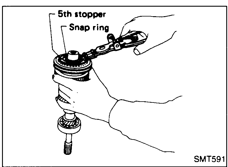
- 8Select proper snap ring of 5th synchronizer hub to minimize clearance of groove in input shaft and install it.Allowable clearance of groove: 0 - 0.1 mm (0 - 0.004 in)Snap ring of 5th synchronizer: Refer to S.D.S.
 SMT591
| Specification | Value |
|---|---|
| Allowable clearance of groove — input shaft front bearing snap ring | 0 - 0.1mm (0 - 0.004 in) |
| Allowable clearance of groove — 5th synchronizer hub snap ring | 0 - 0.1mm (0 - 0.004 in) |
Allowable clearance of groove — input shaft front bearing snap ring
0 - 0.1mm (0 - 0.004 in)
Allowable clearance of groove — 5th synchronizer hub snap ring
0 - 0.1mm (0 - 0.004 in)
See also
S.D.S. · Disassembly