
BRAKE HYDRAULIC LINE
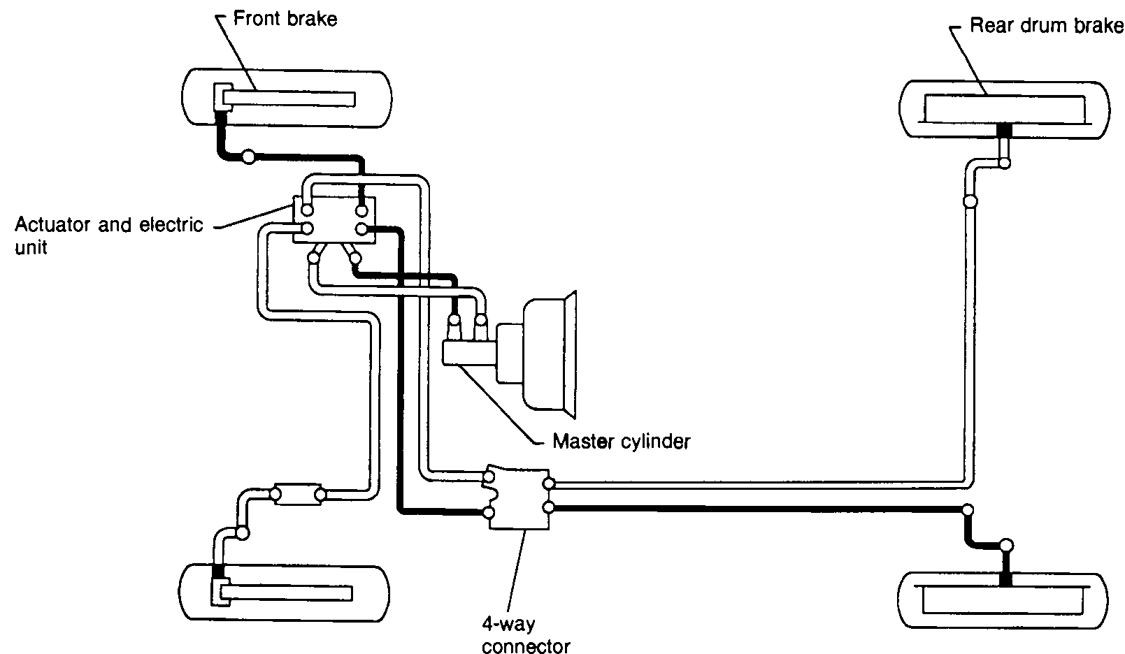
BR-7005parts diagramTwo diagrams shown: one for vehicles without ABS (with load sensing valve), one for vehicles with ABS (with actuator and electric unit replacing load sensing valve).
Without anti-lock system (ABS)
Component LocationFig. fig1
Brake hydraulic line routing for vehicles without ABS. Master cylinder feeds the 4-way connector and load sensing valve which distributes to front brakes and rear drum brakes.
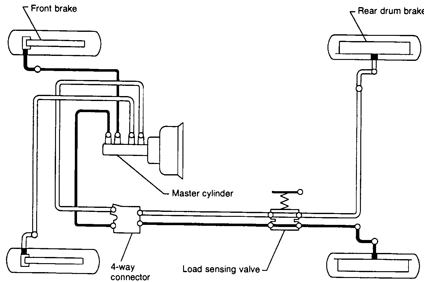
1Front brake(top-left and bottom-left)
2Master cylinder(center)
34-way connector(lower-center)
4Load sensing valve(right of 4-way connector)
5Rear drum brake(top-right and bottom-right)
With anti-lock braking system (ABS)
Component LocationFig. fig2
Brake hydraulic line routing for vehicles with ABS. Master cylinder feeds the ABS actuator and electric unit, which distributes pressure to front brakes and rear drum brakes via the 4-way connector.
NBR387
1Front brake(top-left and bottom-left)
2Actuator and electric unit(left of master cylinder)
3Master cylinder(center)
44-way connector(below master cylinder)
5Rear drum brake(top-right and bottom-right)