
ANTI-LOCK BRAKING SYSTEM — Removal and Installation (Cont'd) — ECU / Actuator / Actuator Relays
BR-42prose procedureRelay identification by colour: BLACK = motor relay, WHITE = solenoid valve relay — printed on the relay body inside the actuator relay cover.
Removal and Installation (Cont'd)
ELECTRONIC CONTROL UNIT
NOTE
Location:
LHD: Front driver side wheel house inner.
RHD: Front passenger side behind glove box.
Removal — ACTUATOR
- 1Disconnect battery cable.
- 2Remove air cleaner.
- 3Drain brake fluid. Refer to "Changing Brake Fluid" in "CHECK AND ADJUSTMENT".
- 4Apply different colored paint to each pipe connector and actuator to prevent incorrect connection.
- 5Disconnect harness, brake pipes and remove fixing nuts and actuator ground cable.
 UBR075
Installation — ACTUATOR
CAUTION
After installation, refill with clean, unused brake fluid. Then bleed air. Refer to "CHECK AND ADJUSTMENT" and "AIR BLEEDING" respectively.
- 1Tighten actuator ground cable.
- 2Connect brake pipes temporarily.
- 3Tighten fixing nuts.
- 4Tighten brake pipes.
- 5Refit air cleaner.
- 6Connect harness and battery cable.
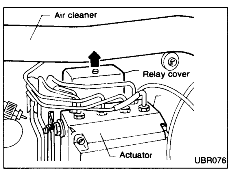
Removal and Installation — ACTUATOR RELAYS
NOTE
BLACK: Motor Relay
WHITE: Solenoid Valve Relay
- 1Disconnect battery cable.
- 2Remove air cleaner.
- 3Remove actuator relay cover.
 UBR076
 - 4Remove connector. Then remove relays.
| Specification | Value |
|---|---|
| Actuator securing nut | 18 - 20N·m (1.8 - 2.0 kg·m, 13 - 14 ft·lb) |
| Brake-tube nut | 15 - 18N·m (1.5 - 1.8 kg·m, 11 - 13 ft·lb) |
Actuator securing nut
18 - 20N·m (1.8 - 2.0 kg·m, 13 - 14 ft·lb)
Brake-tube nut
15 - 18N·m (1.5 - 1.8 kg·m, 11 - 13 ft·lb)
See also
CHECK AND ADJUSTMENT Changing Brake Fluid · AIR BLEEDING