
FRONT DISC BRAKE — Inspection — Rotor (Cont'd) / Assembly / Installation
BR-20prose procedureHub-fix uses two M12 × 1.25 nuts (wheel-stud thread); thickness-variation spec is checked at minimum 8 positions per revolution.
Inspection — Rotor (Cont'd)
RUNOUT
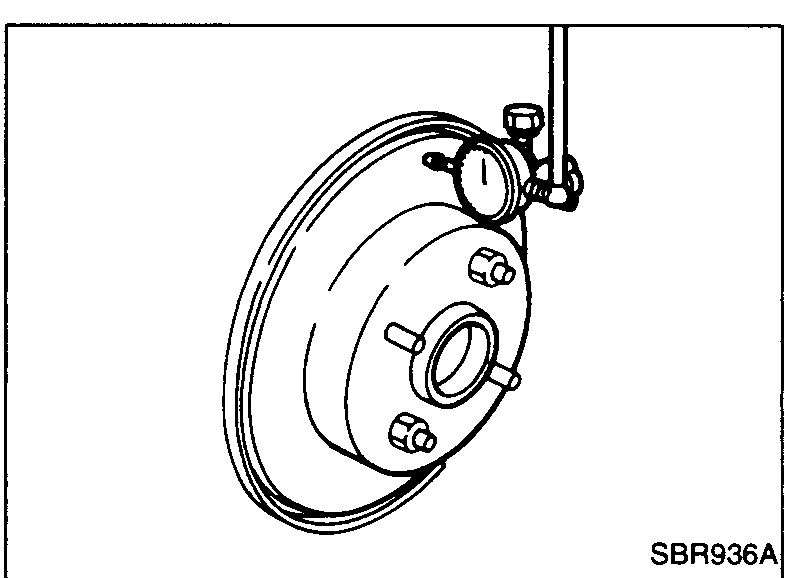
- 1Secure rotor to wheel hub with two nuts (M12 × 1.25).
 SBR936A
 - 2Check runout using a dial indicator.
NOTE
Make sure that axial end play is within the specifications before measuring. Refer to section FA.
| Specification | Value |
|---|---|
| Front rotor — maximum runout (total indicator reading at center of pad-contact surface) | 0.07mm (0.0028 in) |
Front rotor — maximum runout (total indicator reading at center of pad-contact surface)
0.07mm (0.0028 in)
THICKNESS
| Specification | Value |
|---|---|
| Standard rotor thickness | 12mm (0.47 in) |
| Minimum rotor thickness (repair limit) | 10mm (0.39 in) |
| Maximum thickness variation (≥8 positions) | 0.02mm (0.0008 in) |
Standard rotor thickness
12mm (0.47 in)
Minimum rotor thickness (repair limit)
10mm (0.39 in)
Maximum thickness variation (≥8 positions)
0.02mm (0.0008 in)
Assembly
CAUTION
When fitting piston seal to cylinder body, pay attention to piston seal direction.
- 1With dust seal fitted to piston, insert dust seal into groove on cylinder body and install piston.
 SBR574
 - 2Properly secure dust seal.
Installation
CAUTION
• Refill with new brake fluid "DOT 4".
• Never reuse drained brake fluid.
• Always renew brake hose union copper washers.
• Prior to installation of hose to caliper, remove any fluid from sealing surfaces of copper washers.
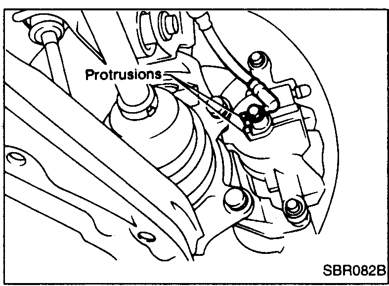
- 1Install brake hose to caliper securely.
 SBR082B
 - 2Install all parts and secure all bolts.
- 3Bleed air. Refer to "Bleeding Procedure" in "AIR BLEEDING".