
ENGINE COOLING SYSTEM - Thermostat Housing / Radiator / Electrical Cooling Fan
LC-12parts diagramRadiator drawing depicts N.CVT cooler hose loop — applies to CVT-equipped variants.
Thermostat Housing
INSPECTION
Visually inspect for water leaks. If there is leakage, apply liquid gasket.
INSTALLATION
When installing thermostat housing, apply liquid gasket as shown.
| Specification | Value |
|---|---|
| Liquid gasket bead widthThermostat housing mating surface | 2.0 - 3.0mm (0.079 - 0.118 in) |
Liquid gasket bead widthThermostat housing mating surface
2.0 - 3.0mm (0.079 - 0.118 in)
Radiator
Parts DiagramFig. fig2
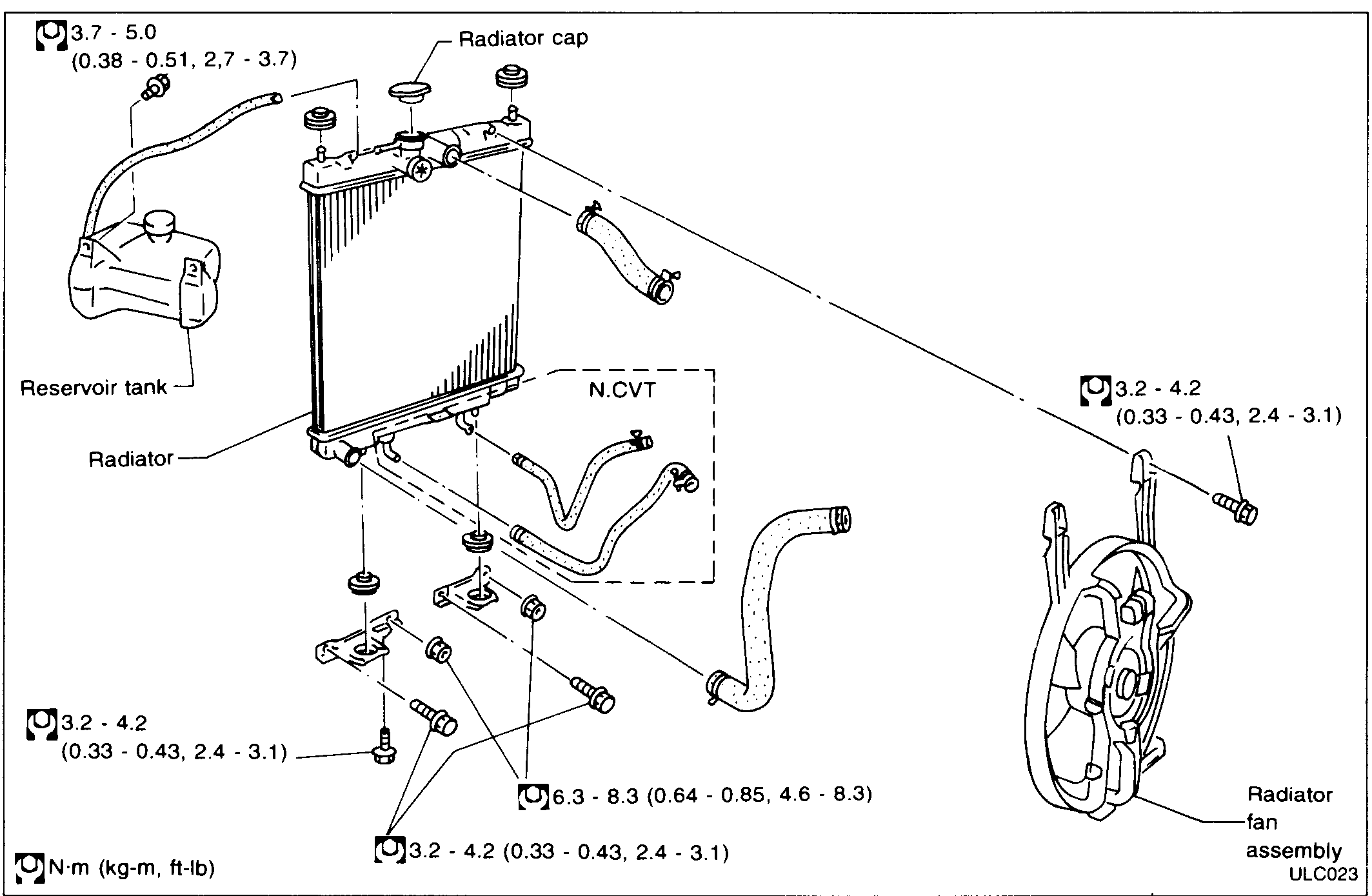
| Specification | Value |
|---|---|
| Reservoir tank bracket boltTightening torque | 3.7 - 5.0N·m |
| Radiator lower mount boltTightening torque | 3.2 - 4.2N·m |
| Radiator upper mount / hose clamp boltTightening torque | 6.3 - 8.3N·m |
| Radiator support bolt (small)Tightening torque | 3.2 - 4.2N·m |
| Radiator fan assembly mounting boltTightening torque | 3.2 - 4.2N·m |
Reservoir tank bracket boltTightening torque
3.7 - 5.0N·m
Radiator lower mount boltTightening torque
3.2 - 4.2N·m
Radiator upper mount / hose clamp boltTightening torque
6.3 - 8.3N·m
Radiator support bolt (small)Tightening torque
3.2 - 4.2N·m
Radiator fan assembly mounting boltTightening torque
3.2 - 4.2N·m
CAUTION
When filling radiator with coolant, refer to MA section.
Electrical Cooling Fan
For trouble diagnosis of radiator fan control, refer to section EF & EC.