
POWER STEERING GEAR AND LINKAGE
ST-23prose procedureLHD vs RHD removal procedures differ (left- vs right-hand wheel arch). Tyre fitment 175/60-13 uses short-travel rack; all others use standard length rack.
Removal (Cont'd)
- 10Remove steering gear mounting bolts.
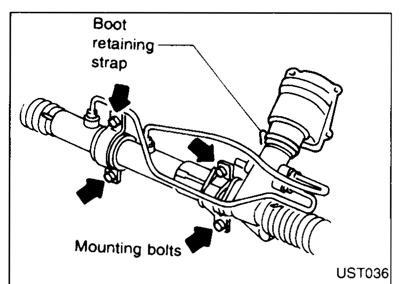 ST036
ST036 - 11Slacken dust boot retaining strap and remove dust boot from pinion.
- 12For LHD vehicles, rotate gear and displace through right-hand wheel arch until left-hand tie rod is clear to drop out through bottom of engine bay, then remove assembly. For RHD vehicles, rotate gear and displace through left-hand wheel arch until right-hand tie rod is clear to drop out through bottom of engine bay, then remove assembly.
 ST5818
Installation
- 1Installation is basically the reverse procedure to removal.
- 2Ensure there are no cracks or splits in any of the dust boots; all fluid lines and glands are secure and free from leaks prior to installation.
- 3Ensure that the correct mounting clamps and rubbers are used for the power steering rack and they are oriented correctly with the oval holes located at the top.
- 4When replacing steering gear, ensure correct rack length is selected.Short travel is for vehicles fitted with wide tyres (175/60-13).Standard length rack is used for all other vehicles.
- 5When fitting rack mounting bolts, initially install bolts (1) and (2) so that the mating parts are not clamped and then install bolts (3) and (4) and tighten in the sequence shown.
 ST026
ST026 - 6Ensure that the steering gear is correctly aligned in housing brackets, and that transfer tubes do not foul bulkhead or subframe.
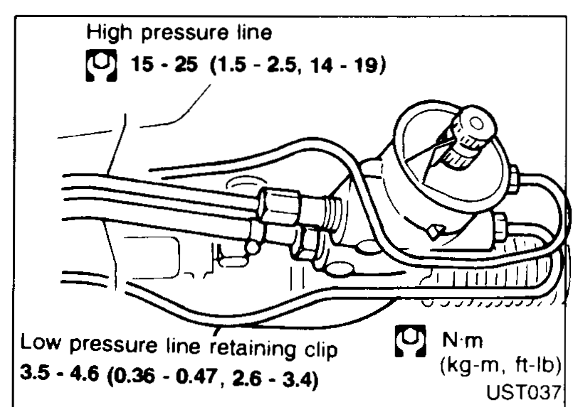
- 7Refit high and low pressure fluid lines. Ensure high pressure line gland is tightened to the recommended torque. Ensure low pressure line is fitted up to flare nut before tightening hose retaining clip.Excessive tightening can damage threads or connector O-ring.The O-ring on low pressure pipe connector is larger than for high-pressure connector. Take care to install the correct O-ring.
 ST037
ST037
CAUTION
Excessive tightening can damage threads or connector O-ring.
The O-ring on low pressure pipe connector is larger than for high-pressure connector. Take care to install the correct O-ring.
| Specification | Value |
|---|---|
| High pressure lineTightening torque | 19 - 25N·m |
| Low pressure line retaining clipTightening torque | 3.0 - 4.6N·m |
High pressure lineTightening torque
19 - 25N·m
Low pressure line retaining clipTightening torque
3.0 - 4.6N·m