
TROUBLE DIAGNOSES — Wiring Diagram – Heater / Main Power Supply and Ground Circuit Check
HA-44wiring diagramWiring Diagram — Heater
Heater wiring diagram
Components (10)
eccs_control_unitjoint_f22fuse_blockign_acc_onjoint_m54blower_motorfan_switchblower_resistorjoint_m10joint_m56
Connections (10)
ign_acc_on
ign_acc_onfuse_block:15A_IGN_ACC_ON??
fuse_block
fuse_block:15A_IGN_ACC_ONblower_motorL/R
blower_motor
blower_motorfan_switch:1B
fan_switch
fan_switch:5blower_resistorL/R
fan_switch:4blower_resistorL/B
fan_switch:3blower_resistorL/Y
fan_switch:2joint_m10B
fan_switch:2joint_m56B
eccs_control_unit
eccs_control_unitjoint_f22LG/R— (E.F.I. harness)
joint_f22
joint_f22joint_m54LG/R— (Main harness)
Main Power Supply and Ground Circuit Check
POWER SUPPLY CIRCUIT CHECK FOR A/C SYSTEM
Check power supply circuit for air conditioning system. Refer to "POWER SUPPLY ROUTING" in EL section and A/C ELECTRICAL CIRCUIT.
THERMO CONTROL AMP. CHECK
Check power supply circuit for thermo control amp. with ignition switch ON.
Thermo control amp. power-supply voltage check
- 1Disconnect thermo control amp. harness connector.
 RHA439D
 - 2Connect voltmeter from harness side.
- 3Measure voltage across terminal No. 34 and body ground.
Thermo control amp. — voltage measurement
34
Voltmeter terminal (−)Body ground
VoltageApprox. 12 V
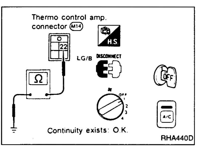
Check body ground circuit for thermo control amp. with ignition switch OFF, A/C switch ON and fan switch ON.
Thermo control amp. body-ground continuity check
- 1Disconnect thermo control amp. harness connector.
 RHA440D
 - 2Connect ohmmeter from harness side.
- 3Check for continuity between terminal No. 22 and body grond.
Thermo control amp. — continuity measurement
22
Ohmmeter terminal (−)Body ground
ContinuityYes