
DISCHARGING, EVACUATING, CHARGING AND CHECKING — Evacuation / Checking Airtightness / Charging Refrigerant
HA-18prose procedureEvacuation
Evacuation procedure
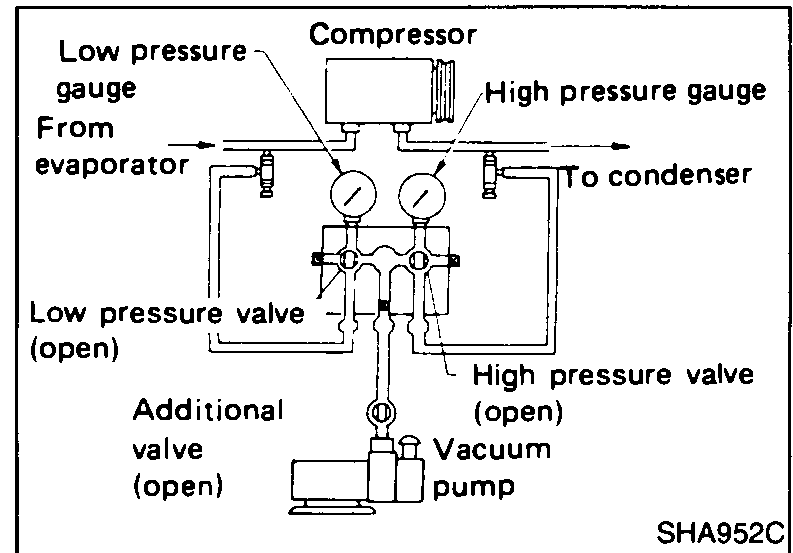
- 1Completely tighten low pressure and high pressure adapter valves.
 SHA952C
 - 2Open high and low pressure valves of manifold gauge set and additional valve.
- 3Run vacuum pump.
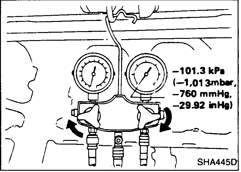
- 4Perform evacuation for more than five minutes to stabilize the vacuum inside the system. Check to ensure that the low pressure gauge indicates -98.6 to -101.3 kPa (-986 to -1,013 mbar, -740 to -760 mmHg, -29.13 to -29.92 inHg).
 SHA445D
 - 5Shut off high and low pressure valves and additional valve.
Checking airtightness
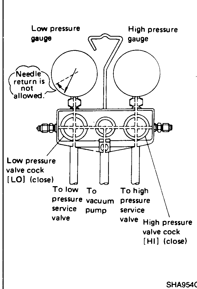
- 1Shut off high and low pressure valves and additional valve, and leave the system as it is for 5 to 10 minutes.
 SHA954C
 - 2Make sure that the needle of low pressure gauge will not move back toward atmospheric pressure side (gauge pressure 0).
IMPORTANT
If any reverse movement is noted, it indicates poor system airtightness. Service the system until airtightness is complete. If pressure changes approx. 13.3 kPa (133 mbar, 100 mmHg, 3.94 inHg) in 10 minutes, the refrigerant in the system will be exhausted in about one month.
EVACUATION
If no abnormality is found during airtightness check, perform evacuation again for more than 20 minutes.
Evacuation (second stage)
- 1Run vacuum pump.
- 2Open high and low pressure valve and additional valve.
- 3Evacuate for more than 20 minutes.
- 4Close high and low pressure valves and additional valve.
Charging Refrigerant
Setting of charging cylinder
- 1Make sure that inlet and outlet valves of charging cylinder are closed.
 RHA677B
 - 2Slowly open liquid line valve of refrigerant tank.
- 3Slowly open inlet valve of charging cylinder.
IMPORTANT
The refrigerant will flow into the sight glass of charging cylinder as inlet valve is opened.