
CHECK AND ADJUSTMENT — Front Wheel Alignment (Cont'd)
FA-5prose procedureCamber/caster/kingpin specs differ between 1.0 L and 1.3 L variants.
Front Wheel Alignment (Cont'd)
CAMBER, CASTER AND KINGPIN INCLINATION
IMPORTANT
Camber, caster and kingpin inclination are preset at factory and cannot be adjusted.
Camber, caster and kingpin inclination measurement
- 1Measure camber, caster and kingpin inclination of both right and left wheels with a suitable alignment gauge.
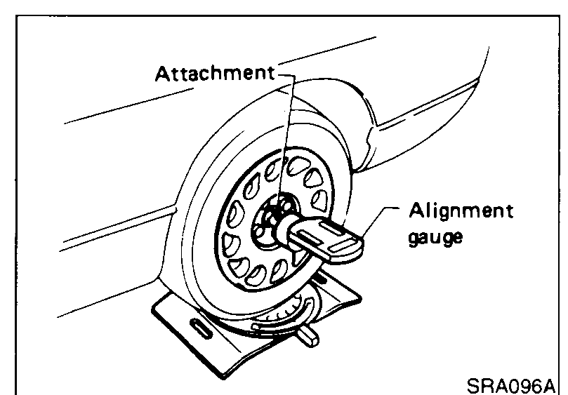 SRA096A
 - 2If camber, caster and kingpin inclination are not within specification, inspect and replace any damaged or worn front suspension parts.
Camber, caster and kingpin inclination
Camber
1.0 L−0°26' to 1°4'
1.3 L−0°22' to 1°8'
Caster (+ve)
1.0 L1°31' to 3°1'
1.3 L1°34' to 3°4'
Kingpin inclination
1.0 L11°52' to 13°22'
1.3 L11°47' to 13°17'
TOE-IN
Toe-in measurement and adjustment
- 1Draw a base line across the tread.After lowering front of vehicle, move it up and down to eliminate friction, and set steering wheel in straight-ahead position.
 SMA123
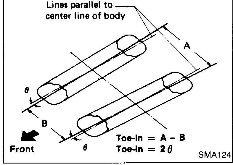
 - 2Measure toe-in. Measure distance "A" and "B" at the same height as hub center.Total toe-in (Unladen): A − B = −0.5 to 1.5 mm (0.02 to 0.06 in) toe-in (positive); 2θ = −0°5' to 0°16' toe-in (positive)
 SMA124
 - 3Adjust toe-in by varying the length of steering tie-rods.
 UFA037
 - 3(1)Loosen lock nuts.
| Specification | Value |
|---|---|
| Total toe-in (Unladen), A − Btoe-in (positive) | −0.5 to 1.5mm (0.02 to 0.06 in) |
| Total toe-in (Unladen), 2θtoe-in (positive) | −0°5' to 0°16' |
Total toe-in (Unladen), A − Btoe-in (positive)
−0.5 to 1.5mm (0.02 to 0.06 in)
Total toe-in (Unladen), 2θtoe-in (positive)
−0°5' to 0°16'