
FUEL SYSTEM — Fuel Gauge Sender Unit Installation (Cont'd) / Fuel Pump Removal
FE-7prose procedureFuel Gauge Sender Unit Installation (Cont'd)
Fuel gauge sender unit installation (continued)
- 4Fit access cover to fuel tank, ensuring that arrow on access cover aligns with mark on tank.Be sure not to disturb the position of the seal.
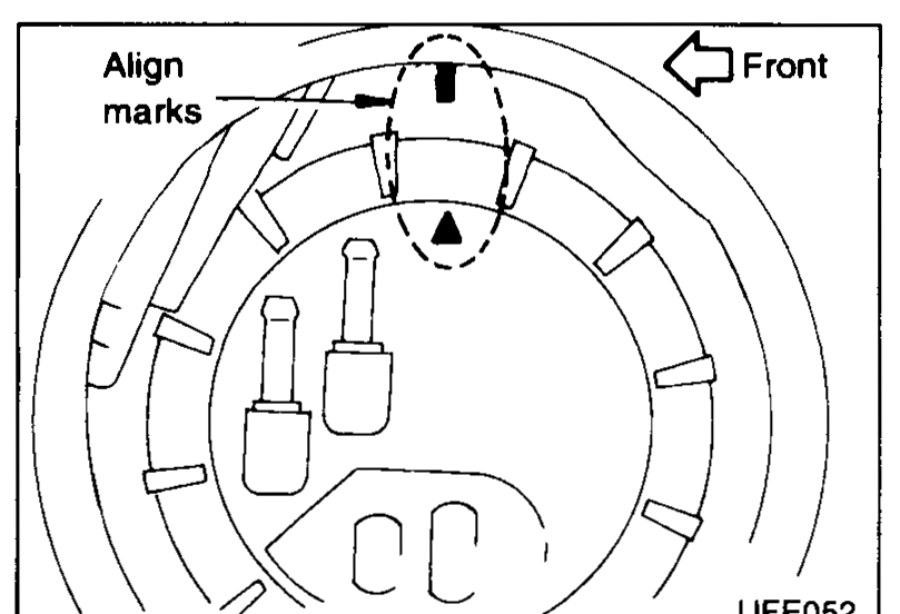 UFE052
 - 5Fit and torque-tighten the locking ring, using SST KV999G0010. Tightening torque: 30 - 35 N·m (3.1 - 3.6 kg-m, 22 - 26 ft-lb)Tightening torque: 30 - 35 N·m (3.1 - 3.6 kg-m, 22 - 26 ft-lb)
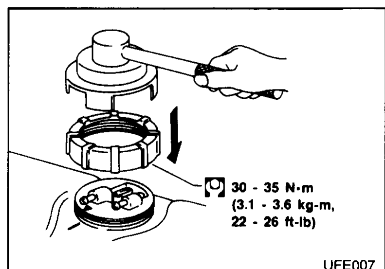 UFE007
 - 6Recheck alignment of access cover marking and fuel tank marking.
- 7Refit fuel gauge connector and fuel pump connector.
 UFE048
 - 8Refit yellow-marked fuel feed hose to fuel feed port, and white-marked fuel return hose to fuel return port. Both ports are marked with an arrow to indicate the direction of the fuel flow.Hose fitting clips should not touch any part of fuel tank and should be 2 to 10 mm (0.08 to 0.39 in) from hose ends.
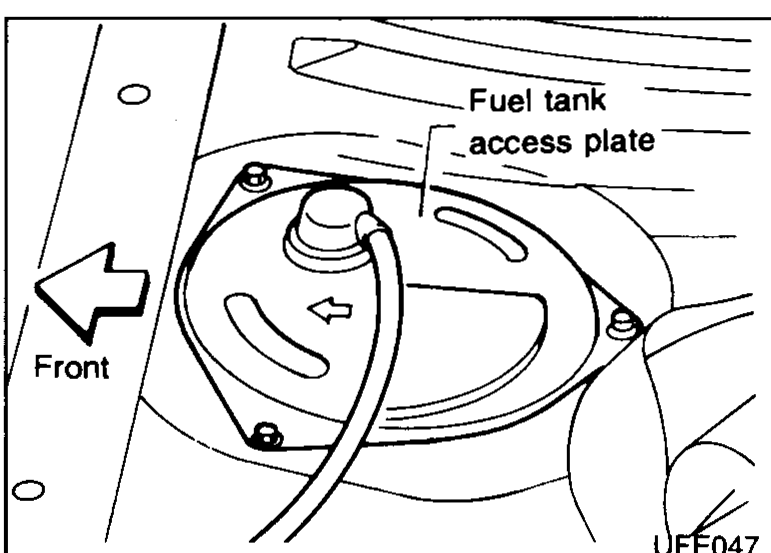
- 9Refit inspection hole plate.
 UFE047
 - 10Refit rear seat cushion.
- 11Reconnect battery.
- 12Refit fuel filler cap.
| Specification | Value |
|---|---|
| Locking ring | ≈294 - 343N·m |
| Hose fitting clip clearance from hose endShould not touch any part of fuel tank | 2 to 10mm (0.08 to 0.39 in) |
Locking ring
294 - 343N·m
Hose fitting clip clearance from hose endShould not touch any part of fuel tank
2 to 10mm (0.08 to 0.39 in)
Fuel pump removal
- 1Remove fuel tank access cover. Refer to "Fuel Gauge Sender Unit Removal".
- 2If "Consult" is not available, pump out the tank through the tank access aperture.
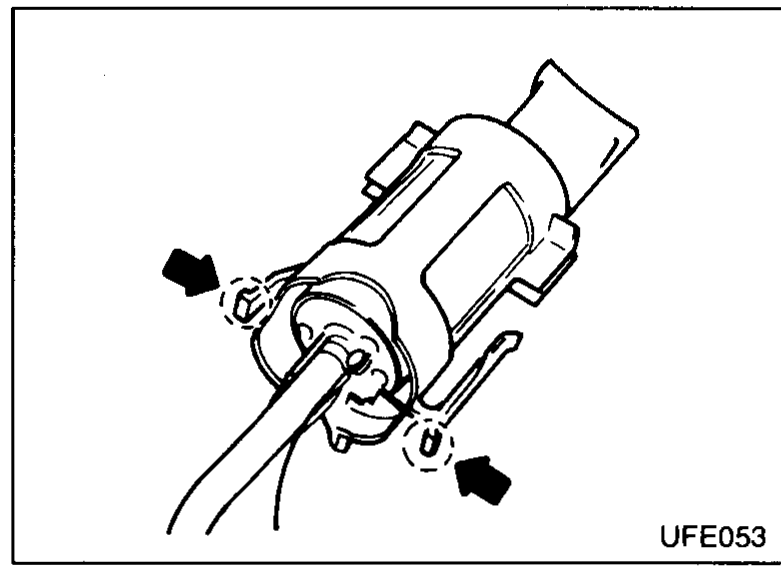
- 3Push the clips as shown and remove fuel pump and its housing from the support bracket.
 UFE053
See also
Fuel Gauge Sender Unit Removal