
FUEL SYSTEM — Fuel Pressure Release / Fuel Gauge Sender Unit Removal
FE-5prose procedureFuel pump fuse location differs between Left-hand drive and Right-hand drive fuse boxes.
WARNING
Before disconnecting any fuel line, release fuel pressure.
Fuel Pressure Release
Fuel pressure release using Consult
- 1Perform "FUEL PRESSURE RELEASE" in "WORK SUPPORT" mode and release fuel pressure to zero.
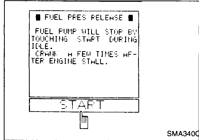 SMA340C
 - 2Turn ignition switch off.
Fuel pressure release without Consult
- 1Remove fuse for fuel pump.
 UMA025
 - 2Start engine.
- 3After engine stalls, crank engine two or three times to make sure that fuel pressure is released.
- 4Turn ignition switch off and install fuse for fuel pump.
Fuel gauge sender unit removal
- 1Remove fuel filler cap.
- 2Release fuel pressure from fuel feed hose. Refer to "Fuel Pressure Release".
- 3If "Consult" is available, disconnect fuel hose from fuel filter and empty fuel tank in "Active Test" mode (Fuel pump relay "ON"). Reconnect fuel hose. If "Consult" is not available, go to step 4.
- 4Disconnect battery.
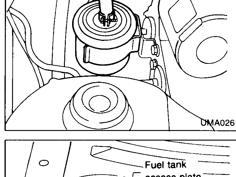
- 5Remove rear seat cushion. Fold towards front seats or remove altogether, depending on specification.
 UMA026
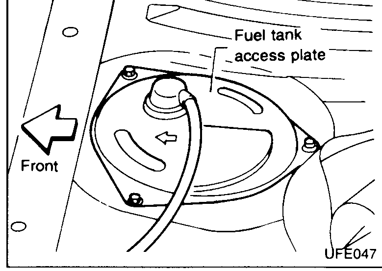
 - 6Remove fuel tank access plate.
 UFE047
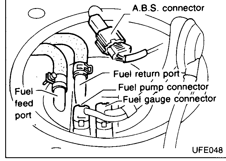
 - 7Disconnect fuel gauge connector and fuel pump connector through aperture.
 UFE048
 - 8Disconnect fuel feed hose and fuel return hose through aperture. Note that ports and hoses are marked to facilitate correct re-assembly. Plug hose and pipe openings to prevent entry of dust and dirt.
See also
Fuel Pressure Release